1
\$\begingroup\$

I'm trying to build a circuit that lights up a LED when a battery connected to it is full charged. I found LM358 lying around so I plan to use it as a comparator. I want a 3.7v using a voltage divider, I don't mind if it's less or more a little. I already have some 470ohm resistors. so the other resistor I want is around 165ohms and the standard value resistor is 160ohms and I will get around 3.73v across the 470ohm resistor.

What I wanted to know is how do I choose the resistor values in ohms or kohms, or in mohms? since there are 47k and 16k I also can use them right? but what is the drawback? I know that a comparator/op-amp use a little bit current in its inputs, so what should I be care about choosing the resistor values? Is there something in the LM358 datasheet that it can help to choose me the values between ohms,kohms,mohms ?

LM358 Datasheet

\$\endgroup\$
1
  • 1
    \$\begingroup\$ You need to have sufficient current flowing to drive the leds. \$\endgroup\$
    – Solar Mike
    Commented Jul 1, 2018 at 7:32

2 Answers 2

3
\$\begingroup\$

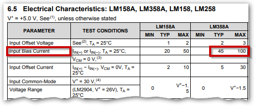
enter image description here

Figure 1. The LM358 input bias current parameter.

The input bias current tells you the current that will be supplied by the input pins. (See Figure 16 to understand that the chip will source current due to the PNP input transistors.) It is 100 nA. (I cropped a couple of columns from the data table so the units are missing.)

As with all designs you have a trade-off to consider for your voltage divider. Lower value resistors will make the bias current less of a problem. Higher value resistors will waste less power and this might be critical for a battery-powered application.

If faced with the problem I would consider the following two options:

  • Set the voltage divider current to 100 times that of the bias current so that the divider should be within about 1% of calculated value. That would be 10 µA in this case and for a 5 V supply would give a total divider chain resistance of \$ R = \frac {V}{I} = \frac {5}{10µ} = 0.5 \ \text M\Omega \$. Any values less that this would improve the situation.
  • Assume the typical value of 45 µA and correct the divider to allow for this.
\$\endgroup\$
1
  • 1
    \$\begingroup\$ In addition to Transistor's answer regarding current in the voltage divider, I recommend jansson.us/resistors.html as a quick and easy way to get any desired ratio using standard values of resistor. \$\endgroup\$
    – user131342
    Commented Jul 1, 2018 at 10:49
1
\$\begingroup\$

You don't say how you are going to power the op amp, but if you're doing it with 5 volts or less the circuit may not work under any circumstances.

Look at sections 6.5 and 6.6 of the data sheets, "Voltage Output Swing". For a 30 volt supply, the high output is only guaranteed to read 26 volts. There is no spec for lower voltages. In the worst case, this 4 volt difference (30 minus 26) will apply at lower voltages, and at 5 volts the output will go no higher than 1 volt, which will not turn on any LED.

This may well not be true in your case (almost all parts will do better than their rated minimum) - but you can't count on it. You need to try it out before you spend any more effort on design.

\$\endgroup\$
0

Your Answer

By clicking “Post Your Answer”, you agree to our terms of service and acknowledge you have read our privacy policy.

Not the answer you're looking for? Browse other questions tagged or ask your own question.