2
\$\begingroup\$

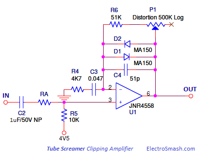
So a friend of mine asked me to evaluate how hard would be to build a guitar effect like the ones described in this thread. The pedal in question is a customization of the Ibanez Tube Screamer. The central part of this effect is providing overdrive (and, with more gain, heavy distortion) by clipping the audio signal with two antiparallel diodes in the feedback path:

Distortion part

MA150 are the diodes in question, ordinary silicon small-signal diodes.

The thread emphasises on the immense improvement of the effect's tonal qualities by replacing the diodes with MOSFETs (presumably by turning the MOSFETs into diodes, gate and source are shorted together).

As it could well be pure audiophilia (you know, the thread contains passages like

If you're into overdrive pedals, you'll know that MOSFET-based OD's are all the rage, for their natural, tube-like response.

)... still you never know, and I'm not 100% how to answer my friend. Can a MOSFET's body diode be all that different from a small-signal silicon discrete one?

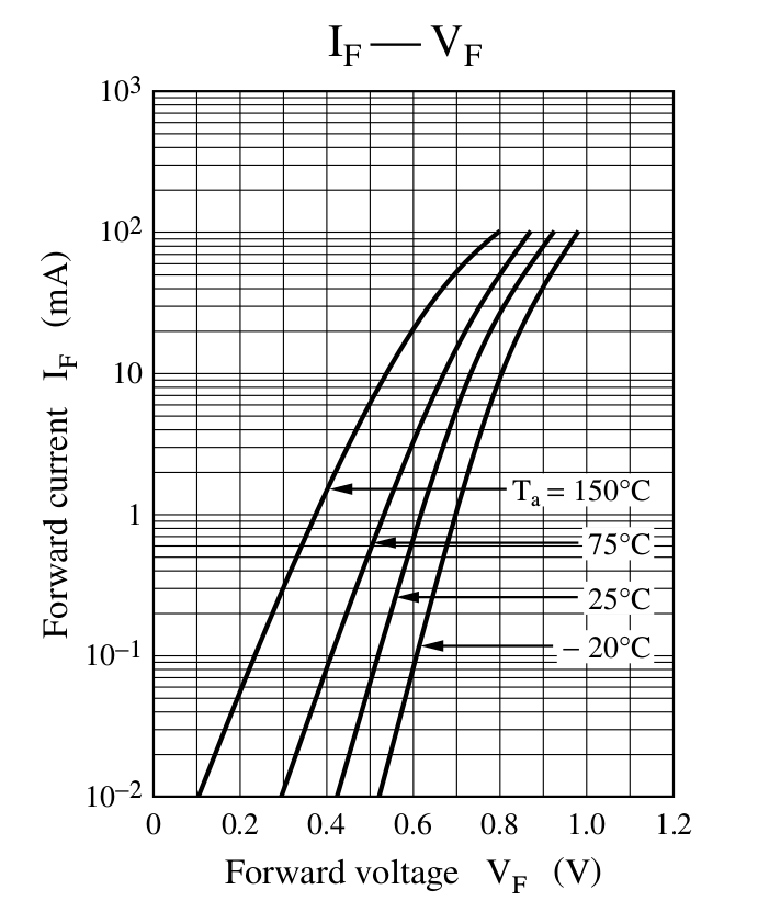
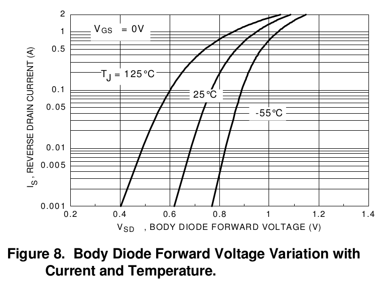
For completeness, here are the V-I curves of the devices in question:

MA150 diode: MA150 V-I curve

BS170 MOSFET's body diode: BS170 body diode V-I curve

\$\endgroup\$
4
  • 4
    \$\begingroup\$ Oh, definitely. A MOSFET body diode has way more defined highs and takes the mud out of the bass. It gives a creamy smoothness to the audio you can't get from anything else. Except maybe oxygen free copper AC line cords. \$\endgroup\$
    – John D
    Commented Jul 3, 2018 at 23:16
  • \$\begingroup\$ I think they are referring to using the MOSFET as an ideal diode, not just using the body diode. This is done by turning on the MOSFET by driving the gate to conduct in one direction without the voltage drop associated with a diode, turning the MOSFET off blocks current from flowing in the opposite direction like a conventional diode. However it takes some control circuitry to make a MOSFET ideal diode. \$\endgroup\$
    – EE_socal
    Commented Jul 3, 2018 at 23:50
  • 1
    \$\begingroup\$ @EE_socal, I don't think they add this extra circuitry, and also: two ideal diodes in antiparallel orientation is equal to a plain wire, isn't it? \$\endgroup\$
    – anrieff
    Commented Jul 4, 2018 at 0:34
  • \$\begingroup\$ No, there will always be at least the forward voltage of a diode in potential difference. \$\endgroup\$ Commented Jul 4, 2018 at 8:52

1 Answer 1

1
\$\begingroup\$

I believe you are not a sound subjectivist - a person who insists he can hear essential, but unmeasurable sound quality quantities, for example "warmth" or "depth" as soon as he sees a vacuum tube which actually has only the filament connected, a couple of extra zeros in the price label, etc...

Of course the distortion characteristics of that clipping circuit depends on the diodes. The static If/Vf curve differences are not the whole truth. I believe (haven't measured) that longer storage time (see NOTE 1) causes treble loss when compared to a fast diode. It can be good in some cases and something untolerable in other cases.

Very radical clipping characteristics change is possible by adding one resistor in series with parallel diodes. That can be even worth a new potentiometer. Adding a resistor in series with only one diode makes the clipping non-symmetric and turns the device to a fuzz effect.

I do not know the storage times of the suggested diodes nor mosfet diodes and definitely cannot tell the differences as sound description words. You must build a test circuit. A signal generator and an oscilloscope will help much in analyzing, but a proper musician is needed to judge the value for music. Get the musician after you have found clearly measurable differences.

NOTE1: Minority carriers around a P-N junction can live in semiconductor materials a long time after the forward voltage has been reversed. This is the essence of the slowness of a diode. Some diode datasheets call it "storage time" There is also "reverse recovery time" which is the time needed to build the depletion region, but that is generally shorter in PN diodes.

Diodes which are intended to be used as 50 or 60 Hz high current AC rectifiers in power supplies are often useless in

  • high frequency circuits because they seem to conduct as well to both directions
  • pulse circuits because every time the voltage is turned to reversed, a hefty current pulse is conducted to the unwanted direction

BTW there seems to be no easy to find datasheet available for diode MA 150.

\$\endgroup\$
2
  • \$\begingroup\$ I thought about the reverse recovery time being important, but no, it's 10ns on the MA150, well above audio frequencies. I don't find a mention of storage time characteristic in the datasheet I found though. \$\endgroup\$
    – anrieff
    Commented Jul 4, 2018 at 9:07
  • \$\begingroup\$ @anrieff If you have a MA150 and proper measuring equipment, you can make a series circuit diode+resistor and see, if there is some measurable reverse conducting when you apply few volts pp AC at few kHz. The resistor should be 4,7 kOhm. I believe nothing can be seen in audio range. Simulation is a good starting point, too if you have proper models of the components that you are going to use. \$\endgroup\$
    – user136077
    Commented Jul 4, 2018 at 9:17

Your Answer

By clicking “Post Your Answer”, you agree to our terms of service and acknowledge you have read our privacy policy.

Not the answer you're looking for? Browse other questions tagged or ask your own question.