0
\$\begingroup\$

I'm using a Raspberry Pi in a circuit I'm building that includes a few elements.

Elements in the circuit:

  1. PWM driver to control 3 servos
  2. Mic board for recording
  3. Class D Amplifier that drives 2x3W 4ohm speakers
  4. 4inch HDMI screen

Limitations:

  1. I can use only one power source plugged into the wall to power the whole system. I'm currently using a 5V 10A power supply.
  2. The enclosure is very small so adding space consuming components can be challenging.

Problems:

  1. Driving the servos causes the low voltage indicator to show up on the pi. The power supply is rated for 5V 10A and the peak current draw is ~3A.
  2. The amplifier is picking up noise from the circuit causing an audible hiss/crackle from the speakers.

Things I've tried:

  1. I tried adding large decoupling capacitors - 1000uf/4700uf right at the Pi's power and at entry point of power supply. The Pi is powered from it's GPIO pins. No difference.
  2. Added additional decoupling capacitors in values ranging from 0.1uf to 10uf right before the amplifier. No improvement.
  3. I measured the voltage at the Pi using a multimeter and it never drops below 5.1V even when the servos are being driven, so why the low voltage indicator?
  4. The noise in the circuit isn't caused by the servos. When I remove the servos there is still noise being picked up by the amplifier. Similarly removing the amplifier doesn't help get rid of the low voltage indicator while servos are running.

Things that worked:

  1. The only thing that works is powering the Pi from a different 5V supply and sharing common ground. This gets rid of any noise from the speakers and the low voltage warning. However due to Limitation #1 this is not feasible.

Things I've thought about:

  1. Pairing a higher voltage power supply(12v,24v) with a buck regulator to create 2 +5V rails.Use one rail for Pi and one for servos/audio. Not sure if this is even possible or how it would be done?
  2. Finding a power supply which has two +5V outputs. No luck finding one yet. Also seems overkill.

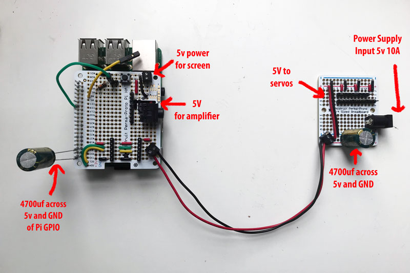
Image of the circuit

enter image description here

What can I do to reduce noise in the circuit to get rid off the low voltage warning and speaker noise?

\$\endgroup\$
7
  • \$\begingroup\$ A supercapacitor packs more capacitance in a small volume. Two in series should handle 5.5 VDC. Combined with a small inductor as in the answer below should make a rock-steady supply for the Pi, with 5 V for servos drawn before the inductor. E.G. amazon.com/Atoplee-10pcs-Capacitor-Monomer-Capacitance/dp/…, \$\endgroup\$ Commented Jul 23, 2018 at 20:55
  • \$\begingroup\$ @DrMoishePippik will the supercaps be in series or parellel(like the circuit below)? Also is the placement similar - CLC or CCL? \$\endgroup\$
    – shekit
    Commented Jul 23, 2018 at 21:09
  • \$\begingroup\$ The diagram would look like that of @uglyoldbob, below, without C1. Drive the servos from the input side, the Pi on the output. \$\endgroup\$ Commented Jul 23, 2018 at 21:23
  • \$\begingroup\$ @DrMoishePippik ok and just to confirm C2 now becomes two supercaps in series? \$\endgroup\$
    – shekit
    Commented Jul 23, 2018 at 21:48
  • \$\begingroup\$ Or one 5.5 V supercap (supercaps have an electrolyte that decomposes at ~2.75 V). \$\endgroup\$ Commented Jul 23, 2018 at 22:12

3 Answers 3

1
\$\begingroup\$

If you change your power source with isolated ground dc-dc converter, you may kill the noise source. Most of the main electical network of the cities are noisy enough.

\$\endgroup\$
0
\$\begingroup\$

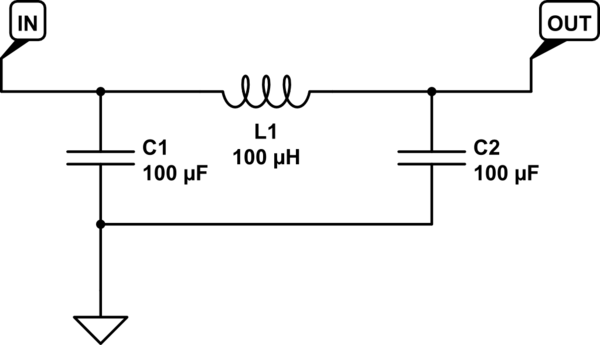
A CLC style pi filter might be effective. I made up some values for the example circuit, so don't count on those exact values being effective.

schematic

simulate this circuit – Schematic created using CircuitLab

\$\endgroup\$
1
  • \$\begingroup\$ Thanks, I'll try this. Is the best way to determine the optimum values for the inductor and capacitors just simple trial and error? \$\endgroup\$
    – shekit
    Commented Jul 23, 2018 at 20:40
0
\$\begingroup\$

Audio does not like switching of any type. Consider for testing purposes trying with a separate power supply for the audio (grounds need to be connected) and see what happens to the noise. If that works they you can consider using a higher voltage wall wart then an an analog regulators well bypassed. Consider placing a CLC style pi filter in front of the regulators. Be careful of the inductor if not properly bypassed it can cause the regulator to oscillate. Because of the capacitance you appear to be using I would consider placing a diode across the regulators with anode to output and cathode to the input. If the input power fails rapidly the diode will protect the regulator from reverse voltage. This is not a problem with some regulators. In the high end audio gear I have the digital power is separate from the audio power.

\$\endgroup\$

Your Answer

By clicking “Post Your Answer”, you agree to our terms of service and acknowledge you have read our privacy policy.

Not the answer you're looking for? Browse other questions tagged or ask your own question.