1
\$\begingroup\$

Currently, I'm working on a Invidia Jetson TX2 dev kit.

I'm trying to power a 12V 2A LED from a 3.3V GPIO. My current system uses a 12V relay with an optocoupler (generic Arduino One), but I'm trying to use a transistor instead.

  1. Using FQP30N60L MOSFET without a load and a 10kΩ pull-down resistor.
  2. Using 2N3904 for driving a 3V blue LED with a 390Ω on 12V (and 10kΩ on gpio<>base)

Both scenarios show that GPIO voltage drops from 3.3V to 1.3v~1.8v when connected. Is that normal or am I doing something wrong?

  • It's not very clear what current can the GPIO supply, but from my understanding it's 1mA (could be wrong).

Thanks!

EDIT: Thanks to 'amb' i understand my readings; thanks :) So after reading some more i have another question: GPIO port is an 'open-drain design' with 100k ohm internal pull-up (other GPIO ports have 20k and 47k), This port can provide 1ma of current.

What is the proper way of driving a 12v (2a max) LED using a MOSFET?

Note: i have added a simple drawing of my setup, i know it wont work, just trying so simulate my problem

EDIT 2: Internal pull-up is 100k ohm

EDIT 3: Is R2 needed here? as its an open drain with internal pull-up, pin wont be floating (i put it as i did in arduino, witch is not the case here)

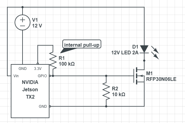
enter image description here

\$\endgroup\$
6
  • \$\begingroup\$ 2A LED, seriously? What does it do, light up the whole neighbourhood? \$\endgroup\$
    – Lundin
    Commented Aug 15, 2018 at 11:56
  • \$\begingroup\$ real time warning light in direct sunlight situations \$\endgroup\$
    – Moos
    Commented Aug 15, 2018 at 12:39
  • \$\begingroup\$ Still doesn't explain 2A. That's enough to drive all LEDs on a well-lit truck. Is it a light bulb? \$\endgroup\$
    – Lundin
    Commented Aug 15, 2018 at 12:43
  • \$\begingroup\$ Anyway, where do you measure the ~1.3V, at the MOSFET or at the CPU pin? Could there be any other components in between besides those in your schematic? \$\endgroup\$
    – Lundin
    Commented Aug 15, 2018 at 12:45
  • \$\begingroup\$ COB led 10w-20w \$\endgroup\$
    – Moos
    Commented Aug 15, 2018 at 12:46

1 Answer 1

2
\$\begingroup\$

Sounds like the GPIO has a pullup (of about 10k) on the Jetson board. Your pulldown is forming a potential divider with this, hence the measured 1.3-1.8V.

\$\endgroup\$
4
  • 1
    \$\begingroup\$ Internal pull-ups should only matter if the port is set as input. In this case, it is an output, so I don't believe this is the problem. External pull-up could be. \$\endgroup\$
    – Lundin
    Commented Aug 15, 2018 at 12:00
  • \$\begingroup\$ I edited the typo in the scheme, R1 is 100K , therefore Vgate is ~0.3v \$\endgroup\$
    – Moos
    Commented Aug 15, 2018 at 12:48
  • 1
    \$\begingroup\$ @Moos But you said it was ~1.3V? Also the internal pull-up should not be active if the port is set as output. \$\endgroup\$
    – Lundin
    Commented Aug 15, 2018 at 14:07
  • \$\begingroup\$ Internal pull-up is always active as its an open-drain design(GPIO pin), otherwise the would be LOW\Floating. 1.3v is caused by internal pull up and R2 acting as a voltage divider (with 20K internal pull up from another pin) \$\endgroup\$
    – Moos
    Commented Aug 16, 2018 at 7:06

Your Answer

By clicking “Post Your Answer”, you agree to our terms of service and acknowledge you have read our privacy policy.

Not the answer you're looking for? Browse other questions tagged or ask your own question.