1
\$\begingroup\$

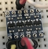
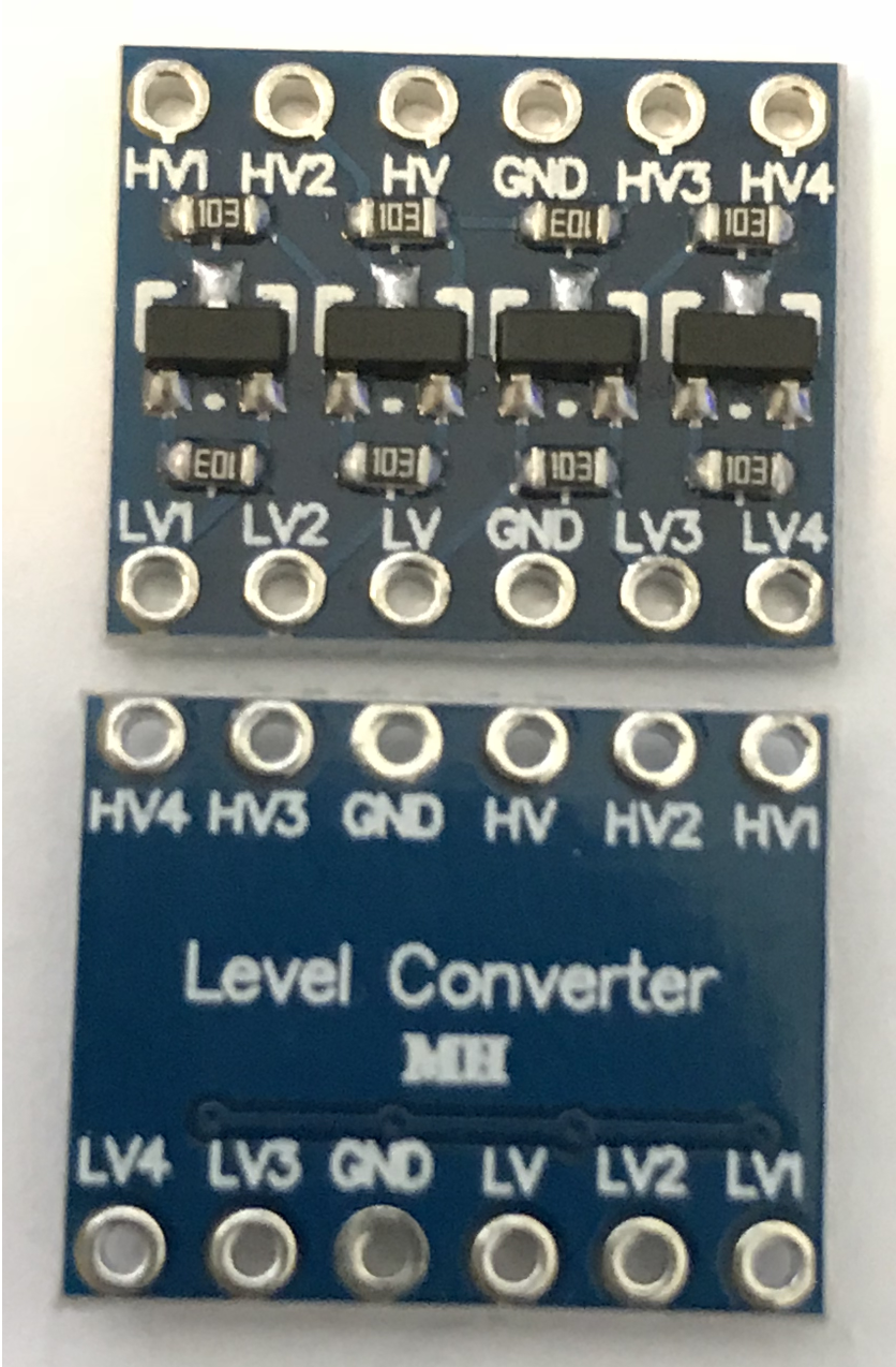
I have a 4-channel logic level converter (it says Level Converter MH on its back and seems to be a very common one for Raspberry Pi and Arduino usage) and wanted to test it's functionality. I don't have a data sheet for it, but its this thing: Link to the product at mepits.com. Here are images of my board: Clearer pictures of board
I use a 545043 YwRobot breadboard power supply, which provides 5v on one side and 3.3v on the other of my breadboard.

On the low-voltage side of my converter I connected LV to + of the 3.3v side of the power supply and GND to -. On the high-voltage side I did the same but to the 5v +/- on the power supply.

I then connected LV1 to +3.3v (directly from the power supply), to simulate HIGH, and expected to measure +5V on HV1 against the GND on the high-voltage side, but my multimeter only showed 2.9v.

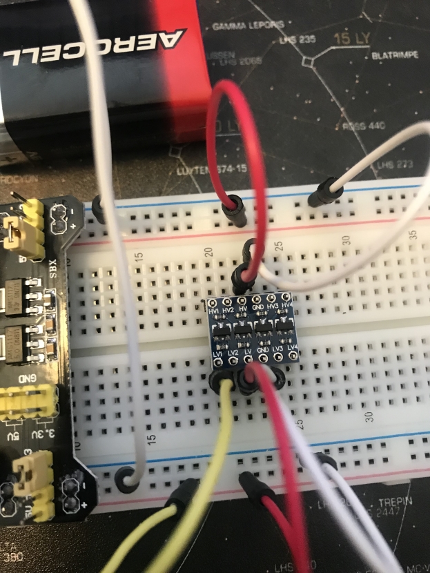
This is my wiring: This is my wiring

The negatives are already connected together on the power supply on the left side, but I added a direct connection to double-check anyways. The upper side is the 5V side, the lower the 3.3V side.

So my question is, did I understand something wrong and wired it up wrongly?

\$\endgroup\$
16
  • 1
    \$\begingroup\$ Willkommen, Sebastian. Can you link to the datasheet for the "Level Converter MH"? I don't know if anyone will know what it is. Also a schematic is the best international description. There is a button on the editor toolbar, if that helps. \$\endgroup\$
    – Transistor
    Commented Aug 13, 2018 at 10:54
  • \$\begingroup\$ Hi Transistor. I don't have a data sheet for it, but I added a link to the board. \$\endgroup\$ Commented Aug 13, 2018 at 11:16
  • \$\begingroup\$ @SebastianP.R.Gingter (a) Can you edit your question and add a couple of good quality, in-focus photos, showing your test setup (preferably with the wiring arranged to be as clear as possible in the photo(s))? (b) Can you supply close-up in-focus photos of just the converter PCB - top & bottom? (c) With the same power connections to the converter as you have now, what happens if you repeat your test using LV2 and measure on HV2, or LV3 & HV3, or LV4 & HV4? (d) What happens if you change from applying +3.3V to LV1, and connect GND to LV1 instead - what do you measure on HV1? \$\endgroup\$
    – SamGibson
    Commented Aug 13, 2018 at 12:23
  • \$\begingroup\$ Images are coming in a few minutes. On all of the 4 HV connectors I measure 2.98 volts when I connect the corresponding LV connector to +3.3V. When I connect them to GND, nothing happens on the HV side. \$\endgroup\$ Commented Aug 13, 2018 at 13:03
  • 1
    \$\begingroup\$ Depends on the relay. If you can't use the GPIO directly, it's likely you can't use the weak 10K ohm pullup output of this either. Generally a relay only needs a firm drive in one direction; this circuit can only firmly drive low. If your relay needs a firm drive high, you need something else. \$\endgroup\$ Commented Aug 13, 2018 at 14:27

1 Answer 1

4
\$\begingroup\$

Thanks for the photos.

The updated photos of the converter's PCB don't reveal any concerns.

However looking at the photo of your breadboard, a problem is clear: You haven't soldered the header pins onto the logic-level converter.

header pins not soldered to logic level converter PCB

That will lead to a variety of potential problems, depending on which connections made good-enough contact, and which do not.

Please solder the header pins to the converter board, re-test, and report back.

\$\endgroup\$
3
  • \$\begingroup\$ Thanks. I will then spend some time later this evening soldering that together. I hoped that sticking it together would be enough to test it out, but if that is not the case, I need to fix that first and check then. \$\endgroup\$ Commented Aug 13, 2018 at 13:27
  • \$\begingroup\$ @Sebastian - "I hoped that sticking it together would be enough to test it out" Unfortunately no. The potential for unexpected poor (high resistance and/or intermittent) and even totally missing connections, means that you cannot rely on "touching" contacts like that. I'm hopeful that this will solve your problem, although at this stage we also can't rule out the possibility of multiple problems, so let's see the test results after the soldering. \$\endgroup\$
    – SamGibson
    Commented Aug 13, 2018 at 13:40
  • 2
    \$\begingroup\$ Thanks a lot. After soldering the pins it worked and I get the 5V on the high ports when I activate the low ones. \$\endgroup\$ Commented Aug 13, 2018 at 18:49

Your Answer

By clicking “Post Your Answer”, you agree to our terms of service and acknowledge you have read our privacy policy.

Not the answer you're looking for? Browse other questions tagged or ask your own question.