0
\$\begingroup\$

I have an Arduino that I want to drive using a 12 V source. Of course, this can be achieved using a voltage regulator or similar solution. Notably, there is a loss in the conversion (at best, this is roughly 5 % with the best switching regulators), which is acceptable. That is all fine.

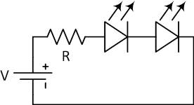
However, I also know that I need to drive a few LEDs. Let us for now ignore the fact that the LEDs work with 3 - 3.6 V and that the source, being a lead-acid battery actually differs in voltage depending on charge. Assume that I have a LED with exactly 3.5 V drop and place two in series with the Arduino, producing a voltage distribution as 3.5 V, 3.5 V and 5 V.

In the below circuit diagram, the Arduino is modelled as a resistance (commonly called an R-duino), but I suspect it is not very accurate.

Exactly, what will happen? My guess is that since LEDs are passive and the Arduino consists of active components, the current draw will be decided by the Arduino, causing the LEDs to shine more brightly when the Arduino draws more current and shine less when the Arduino is in sleep/idle. If we disregard the losses in cables and such, could this solution be considered having 100 % efficiency? If not, then where are the losses (note that light emission is desired and not a considered loss)?

\$\endgroup\$
7
  • 1
    \$\begingroup\$ The assumptions you make are not correct and are critically important. This is a very bad idea. \$\endgroup\$ Commented Aug 17, 2018 at 14:21
  • \$\begingroup\$ Sure, I will not do it :-) I was asking out of curiosity. \$\endgroup\$ Commented Aug 17, 2018 at 14:26
  • \$\begingroup\$ Neither R-duino nor LEDs are 100% efficient - they both produce heat while working (generally considered as a "loss"). \$\endgroup\$
    – glen_geek
    Commented Aug 17, 2018 at 14:42
  • \$\begingroup\$ @glen_geek Yeah, I was thinking of the ideal model. That was not very clear, my bad. \$\endgroup\$ Commented Aug 17, 2018 at 14:47
  • 1
    \$\begingroup\$ Ah, OK, yeah, if you have a 100% quantum efficiency :) (that's a cool diode then; pun intended) \$\endgroup\$ Commented Aug 17, 2018 at 15:20

2 Answers 2

10
\$\begingroup\$

In the below circuit diagram, the Arduino is modelled as a resistance (commonly called an R-duino), but I suspect it is not very accurate.

You're right - it's not very accurate. The Arduino runs on a steady 5 V supply but its current varies depending on its load and what it is doing internally.

Assume that I have a LED with exactly 3.5 V drop ...

Nope, we can't assume that as no LEDs behave this way. There are two problems:

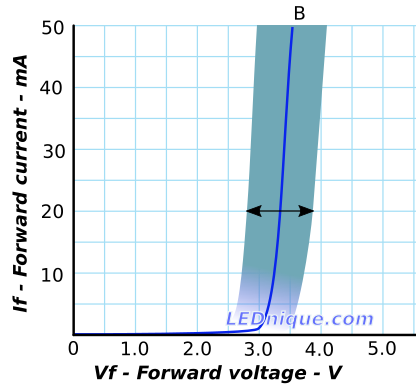
  • VF, the forward voltage, is not a constant but varies with current.
  • VF varies from device to device.

enter image description here

Figure 1. If vs Vf for an LED nominal (blue) and spread (shaded area). Source: Variations in Vf and “binning”.

My guess is that since LEDs are passive and the Arduino consists of active components, the current draw will be decided by the Arduino, causing the LEDs to shine more brightly when the Arduino draws more current and shine less when the Arduino is in sleep/idle.

Correct, but note that when the Arduino is in idle that the If/Vf curve shows us that the voltage drop across the LEDs will decrease. This will increase the voltage to the Arduino and the end result will not be good.

If ... could this solution be considered having 100 % efficiency?

Nothing is 100% efficient, but you are right in that if your load didn't require a particular voltage - or could at least tolerate some variation in voltage - then your circuit makes use of power that would otherwise be wasted in the regulator.

schematic

simulate this circuit – Schematic created using CircuitLab

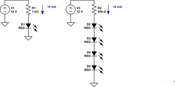
Figure 2. Both circuits use 12 V x 10 mA = 120 mW. The second gives four times as much light for the same energy.

Note that very often we use this idea. If we require an LED indicator on a 12 V supply then 10 V will be lost in the resistor. We can add in additional LEDs without affecting the power budget.

If not, then where are the losses (note that light emission is desired and not a considered loss)?
LEDs dissipate heat as well as light.

\$\endgroup\$
2
  • \$\begingroup\$ I concur — great answer! Also note that typically, if a microcontroller tolerates a large range of input voltages, it's because it integrates a linear voltage regulator for its processor core, and typically only IO transistors are directly driven off VCC. \$\endgroup\$ Commented Aug 17, 2018 at 14:40
  • 2
    \$\begingroup\$ @MarcusMüller I don't think that's all that typical. Many 8-bit processors, run at conservative clock frequencies, can operate over about a 3:1 range in Vdd, and I believe they have no internal voltage regulator for the logic. Of course the processor may not tolerate rapid changes in Vdd. Atmega328 says 1.8~5.5V. By comparison Cortex M7 I'm using has an internal VDDCORE regulator and tolerates 1.7 to 3.6, which is more like 2:1. \$\endgroup\$ Commented Aug 17, 2018 at 15:39
4
\$\begingroup\$

Assume that I have a LED with exactly 3.5 V drop and place two in series with the Arduino, producing a voltage distribution as 3.5 V, 3.5 V and 5 V.

But that assumption is plain wrong.

Diodes have a flat V/I curve the higher you get in current, but for low current draws, the voltage across a diode changes drastically with the current you draw.

Don't use a diode for voltage regulation. Full stop.

\$\endgroup\$
2
  • \$\begingroup\$ Fair enough. So, given an ideal LED with fully flat V/I curve this would be perfectly fine? \$\endgroup\$ Commented Aug 17, 2018 at 14:31
  • \$\begingroup\$ No. The ideal LED doesn't have a flat V/I curve. The ideal LED is still an ideal diode with an exponential current curve. \$\endgroup\$ Commented Aug 17, 2018 at 14:32

Your Answer

By clicking “Post Your Answer”, you agree to our terms of service and acknowledge you have read our privacy policy.

Not the answer you're looking for? Browse other questions tagged or ask your own question.