0
\$\begingroup\$

I'm building a device using STM32F0 MCU.

The whole unit is powered with +24V DC delivered via pretty long cables.

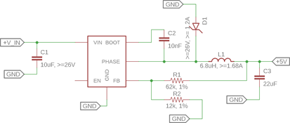
This voltage is passed to the DCDC converter, based on RT8259:

24v do 5v

In the next step 5V is lowered to 3.3V with simple linear regulator (AMS1117-3.3):

5v to 3.3v

This voltage is used to power the MCU (with additional tantalum 4.7uF and ceramic 100nF per pin).

However the microcontroller has a dedicated "VDDA" pin, which according to datasheet is used as input for PLL, ADC etc.

  • Is it required to add additional filter for VDDA?
  • Is LC (10uH + 4.7uF) enough?
  • If the filter is not present, what would happen? Loss of ADC accuracy (how much?) Loss of clock stability?
\$\endgroup\$
2
  • \$\begingroup\$ What type of capacitor are you intending to use on the output of the 1117? These (from various manufacturers) can have stability issues with a very low output ESR. \$\endgroup\$ Commented Aug 18, 2018 at 14:49
  • \$\begingroup\$ Datasheet advises using tantalum capacitor and this is my plan. \$\endgroup\$
    – peku33
    Commented Aug 19, 2018 at 15:05

1 Answer 1

1
\$\begingroup\$

The filter prevents the noise that the digital logic of the MCU itself generates from affecting the sensitive analog sections of the chip — the ADC and the PLL. The rest of the power supply chain doesn't really have much to do with this.

Yes, without the filter your ADC readings and PLL frequency will be "noisier" than necessary. Whether this is important to you — and how much filtering is "enough" — depends on your application.

\$\endgroup\$

Your Answer

By clicking “Post Your Answer”, you agree to our terms of service and acknowledge you have read our privacy policy.

Not the answer you're looking for? Browse other questions tagged or ask your own question.