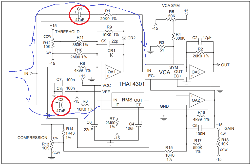
I've built a compressor basing on the all-in-one chip THAT4301. It works well. But I'm still not happy because of the electrolytic capacitor I used in the signal path. My design was based on the reference design of THAT corporation:

The capacitor above is a polarized type. The signal is not biased before. As far as I know, this is a bad use. I also verified my concerns with a simulation. If the signal really containts a negative DC (which this cap tries to avoid) the cap would/should fail or blow.
So I want to replace it with a polarized type. However there is not really a good/small capacitor with such a high value, so I also would like to decrease its value. My circuit works with 10u and I cannot detect any cutoffs in the LF-Response. Still a big cap in the signal path.
I cannot calculate properly the value of this AC-coupling cap because I cannot find the input impedance of VCA (Voltage controlled amp) in the datasheet.
http://www.thatcorp.com/datashts/THAT_4301_Datasheet.pdf
47u would be necessary to pass a 10Hz-AC-Signal if the load had 330 Ohm input impedance! Isn't this freaking low? Can anybody read the input impedance out of the other values in the datasheet?
Why are they recommend a polarized capacitor for a non-biased input? I've seen this also in wikipedia (also frequently mentioned here).
- What kind of possibilities do I have to avoid such big AC-coupling capacitors in the signal path?


