0
\$\begingroup\$

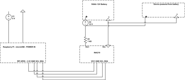
schematic

simulate this circuit – Schematic created using CircuitLab

I want to measure voltage of 12V battery powering something by INA219 connected parallel to this battery and read it with RPi via I2C. Is this possible with INA219? Should I use something else for this? I tried to connect it like I imagine but I had to use 1K resistor between INA219 and battery and my reading then look like this:

Bus Voltage: 0.008 V
Bus Current: 12.305 mA
Power: 0.000 mW
Shunt voltage: 1.240 mV

This way Bus current looks exactly like my voltage provided on Vin

I tried connecting grounds from battery and RPi but there was no change.

Added schematic. Is it clearer now?

\$\endgroup\$
5
  • \$\begingroup\$ What are those red & black lines in your question supposed to represent? If you edit your question there's a button you can click to draw us a proper circuit which might help. \$\endgroup\$
    – brhans
    Commented Aug 23, 2018 at 13:28
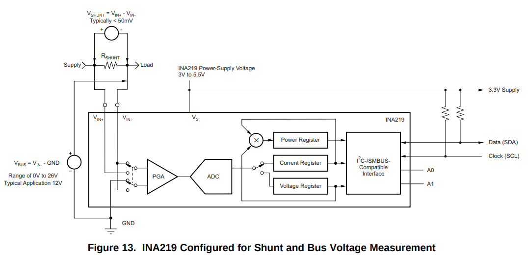
  • \$\begingroup\$ There is a schematic on page 10 of the INA219 datasheet, figure 13. That shows the basic method of connecting the device to monitor your supply voltage and current. If you need to filter the signal, there is figure 14 on the next page. It's not clear to us how you have yours connected. \$\endgroup\$ Commented Aug 23, 2018 at 14:08
  • \$\begingroup\$ Raspberry Pi provides 5v PWM on its supply rails; it's not a PSU. Also consider creating your own circuit because this is extremely unclear. \$\endgroup\$
    – user103380
    Commented Aug 23, 2018 at 14:16
  • \$\begingroup\$ @KingDuken The Raspberry Pi board has a 5V supply but the chip I/O banks are running from 3V3. The PWM output which comes from the GPIO is therefore only 3V3. \$\endgroup\$
    – Oldfart
    Commented Aug 23, 2018 at 15:30
  • \$\begingroup\$ you should be able to meause voltage with just one sense wire; you're using two and incorrectly; you're seeing the voltage drop over the resistor, but the INA can report voltage between gnd and the shunt side w/o current, even if that's not touted. \$\endgroup\$
    – dandavis
    Commented Aug 23, 2018 at 16:08

1 Answer 1

2
\$\begingroup\$

See the schematic below, taken from the datasheet. Reading the datasheet explains that VIN- is the input from which the bus voltage is measured. You should connect this VIN- to your battery's positive terminal if you only want to read voltage. If you want both current and voltage, connect as shown below with "Supply" being your battery positive terminal and "Load" being the power input on your "Device powered from battery".

Edit: to be clear, the measured voltage is VIN- minus the INA219's GND. You will need to connect the INA's GND to the battery's negative terminal, and likely to the RPi's GND as well.

Schematic, Figure 13 from INA219 Datasheet

\$\endgroup\$
2
  • \$\begingroup\$ I don't need current, so I should connect Vin- to + from battery and bridge GND from battery with GND from RPi if I understand correctly. Do you know what happens if Vin- would be greater than 26V? Do you know if there is something like INA219 but with range up to 30V? \$\endgroup\$
    – Kliwer
    Commented Aug 23, 2018 at 18:58
  • \$\begingroup\$ @Kliwer yes that's correct regarding your connections. 30V exceeds the datasheet's listed "Absolute Maximum" of 26V. If you expect the difference between VIN- and GND could be as much as 30V, you will either need 1. Some protection circuitry, or 2. A different power monitor than the INA219. A simple circuit for (1) would be a resistor divider to scale your supply voltage down. You may find a different power monitor to use, but asking for help finding one is off-topic here, sadly. \$\endgroup\$ Commented Aug 23, 2018 at 19:07

Your Answer

By clicking “Post Your Answer”, you agree to our terms of service and acknowledge you have read our privacy policy.

Not the answer you're looking for? Browse other questions tagged or ask your own question.