1
\$\begingroup\$

I am trying to design a 12v,10A buck converter using a with LTC1775 and have gone through the calculations assuming a 40% inductor ripple current and a switching frequency of 150kHz. This gave an inductor value of 10uH and a mosfet with Rds(on) of 0.014ohm. So based on these i have selected IRLR3915 NMOS and 7443558100 inductor.

My main concerns are the following:

  1. Are these two good choices with regards to the output current or they are overkill?
  2. Should i attach a flyback diode across the output incase I have an inductive load like a motor?
  3. Are the Cin and Cout capacitors adequate? Based on datasheet formulas our output voltage ripple is supposedly ~60mv but the simulation only shows ~10mv

here is the circuit schematic: enter image description here
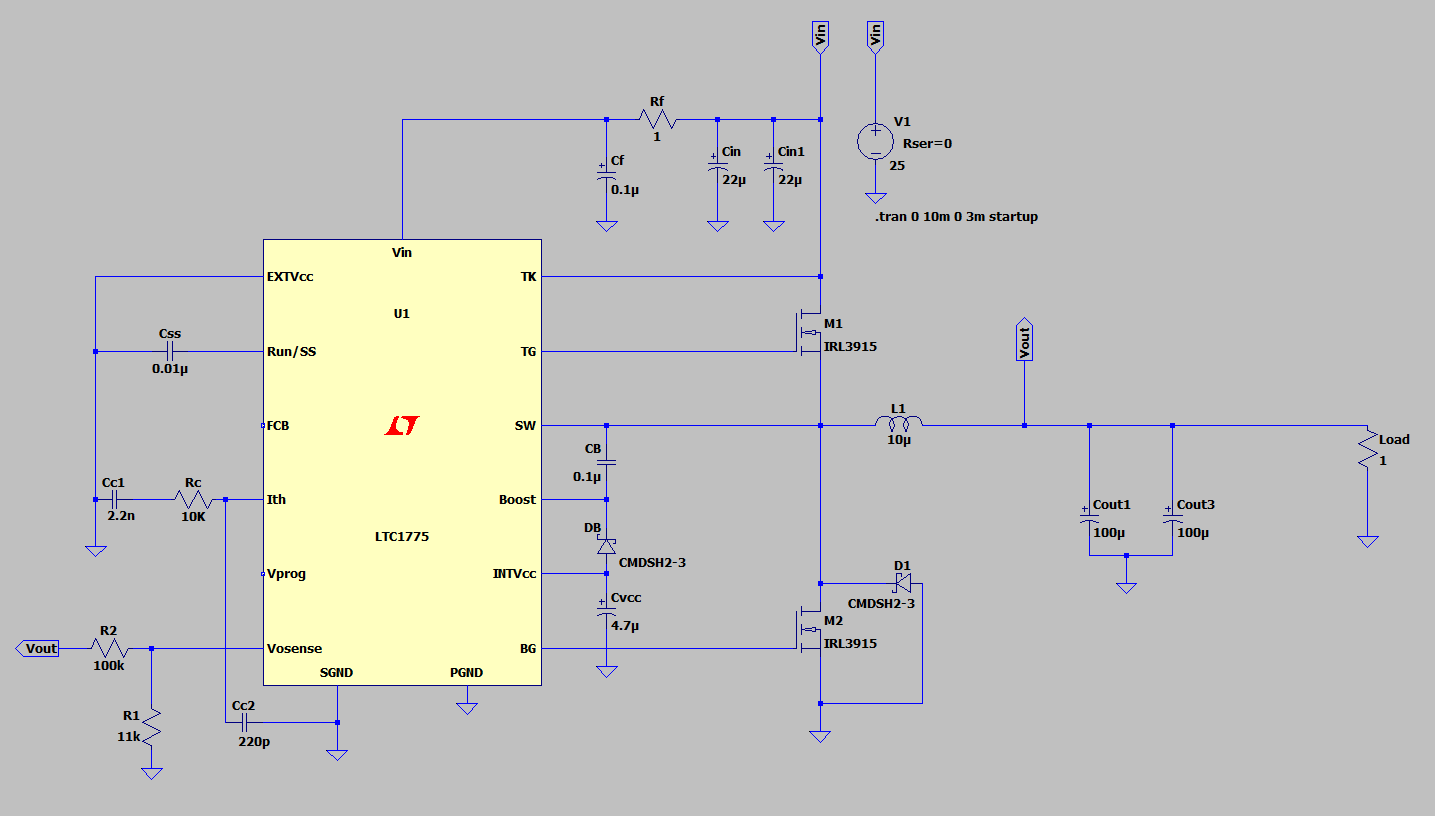
and here is a inductor current on LTspice, as you can see the current does reach ~15A: enter image description here

I can attach the calculations if its needed.

Thank you, I really appreciate your guys help.

\$\endgroup\$
4
  • \$\begingroup\$ I don't think the LTC1775 is quite "man-enough" for 12 volts at 10 amps. \$\endgroup\$
    – Andy aka
    Commented Aug 25, 2018 at 8:19
  • \$\begingroup\$ Please show your PCB layout (all layers), once you get to that point in the project. Pose the question as "can this 15 amp switchreg PCB layout be improved" ???? \$\endgroup\$ Commented Aug 25, 2018 at 10:49
  • \$\begingroup\$ @Andyaka how come? because their own datasheet has a 5V,20A example.however, the chip is fairy expensive. What chip do you suggest that is cheaper and performs the same? \$\endgroup\$
    – Udiny
    Commented Aug 25, 2018 at 14:15
  • \$\begingroup\$ If you find one I don't mind commenting on it. If you look at the selection tool on the ADI website for linear tech devices and enter the 4 needed search parameters and look at the offerings, there are only a few chips that, upon data sheet examination, can produce the volts and amps you want. I'm talking about circuit designs towards the end of each DS and look for a chip that can do 12 volts at 10 amps. Of course you could just rely on the sim but that would be a little naive. This is the voice of experience trying to advise you. \$\endgroup\$
    – Andy aka
    Commented Aug 25, 2018 at 16:57

1 Answer 1

0
\$\begingroup\$

Are these two good choices with regards to the output current or they are overkill?

Use LT powercad (almost all linears DC DC conveters are there) to find optimal components, it is much easier to use and quicker (I'd run this design through myself but haven't the time).

Should i attach a flyback diode across the output incase I have an inductive load like a motor?

Yes, you may also want to consider a filter, the DC DC compensation loop may also present problems from the inductance of the motor. Extra capacitance\filtering may be advantageous with a motor. Because the motor impdeance is hard to determine (and for most motors non-linear) it may require experimentation to get the right compensation\filtering and to avoid voltage dropouts.

Are the Cin and Cout capacitors adequate? Based on datasheet formulas our output voltage ripple is supposedly ~60mv but the simulation only shows ~10mv

You have a fixed load, switch the load in the simulation to determine if it really is adaquate (unless your load really is fixed).

\$\endgroup\$

Your Answer

By clicking “Post Your Answer”, you agree to our terms of service and acknowledge you have read our privacy policy.

Not the answer you're looking for? Browse other questions tagged or ask your own question.