1
\$\begingroup\$

I am trying to determine what exactly is causing the below switching regulator/ DC-DC converter module to not maintain its rated output voltage.

http://www.meanwellusa.com/productPdf.aspx?i=794

I am using the SPBW03G-03, which has a listed maximum output current of 700mA and an output voltage of 3.3V. The input side of the regulator is driven by approximately 45 VDC (32 VAC rectified), which is within the 18-75V input voltage limit.

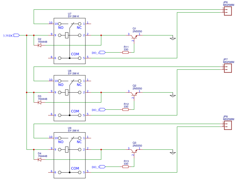
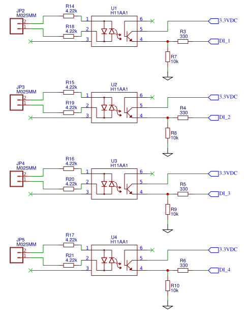
What I have observed is that essentially any load will draw down the output voltage of the regulator. At full load (all inputs on, all outputs/relays activated), I am drawing approximately 150 mA, which is well within the maximum output current of the regulator. The output voltage at my full load case drops to right at 2.98V, and holds there. When the load is removed, the regulator returns to just under 3.3V (measures at about 3.28 with DMM and Oscope). The voltage drop is most pronounced when the three relays are activated (note: the relays are rated for 3V operation) with the rest of the circuit having relatively small impacts on the voltage.

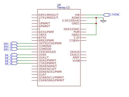
Below are snapshots of my schematic. I should note I have a dummy load in for the TeensyLC just for circuit testing, and am manually triggering inputs and outputs. I apologize for the regulator not being shown, I have not gotten around to adding it to my schematic yet.

enter image description here enter image description here enter image description here

This is the first project for which I have used a switching regulator, so am am wondering if there are any significant pitfalls that I could be missing. The Meanwell documentation is limited, but I know most of the other DC/DC modules suggest input and output capacitors, which I currently have not implemented.

If anyone has some suggestions as to what the issue might be, or what noobie mistakes I have made, I would appreciate the feedback.

\$\endgroup\$
9
  • 1
    \$\begingroup\$ @Ali Chen I know the current because I measured the current with my multi-meter directly at the regulator output. As to your suggestion, I do not have a 20 Ohm resistor, but put two 47 ohm resistors in parallel. Voltage measures at 3.28V. \$\endgroup\$
    – deadeagle
    Commented Aug 26, 2018 at 2:26
  • 1
    \$\begingroup\$ So, with 140 mA known load you have 3.28 V, or 0.6% voltage drop, which is about as specifications says, load regulation 0.5%. But if you load 150 mA (allegedly), you suddenly have 10% drop. Can you find another 47 Ohm resistor, and add it to the previous two in parallel? What voltage would you read? \$\endgroup\$ Commented Aug 26, 2018 at 3:20
  • 1
    \$\begingroup\$ Actually, per your original text, your no-load voltage is 3.28 V. So, you have no measurable voltage drop when the load is 140 mA, which is what is expected, under 0.5%. So, if you use more of of 47-Ohm loads in parallel, how the output voltage behaves? \$\endgroup\$ Commented Aug 26, 2018 at 3:32
  • 1
    \$\begingroup\$ @AliChen I was inspired by your previous comment, so I actually just did that. I put five 47 ohm resistors in series, measured about 340 mA and 3.25V. I also reconnected my circuit and rechecked my measurement to confirm it is somehow only pulling roughly 150 mA. \$\endgroup\$
    – deadeagle
    Commented Aug 26, 2018 at 3:46
  • 1
    \$\begingroup\$ You also say you have no bypass capacitors. The load is inductive. Could it be that the regulator is unstable with inductive loads (relay coils)? Did you try to solder a 100-uF capacitor to 3.3VDC rail on your board? \$\endgroup\$ Commented Aug 26, 2018 at 4:02

2 Answers 2

0
\$\begingroup\$

The Meanwell specs are Single output models:
Load regulation 10~100% ±0.5% Vout. 100% = 3W
1% of 3.3V= 33 mV

Your results: -300mV ~@150mA = 450mW = 15% or 3W
- equivalent to 2 Ohms series resistance.

Possible Conclusion: faulty unit, verify input and connection losses.

\$\endgroup\$
0
\$\begingroup\$

As embarrassing as it is to admit, it looks like the culprit is simply a bad breadboard connection. Replacing two jumper wires at a specific point on my + / - DC rails fixed the problem. Voltage is now 3.24V steady at full load.

I appreciate everyone's input, and will investigate my board a little more thoroughly before asking a question next time.

\$\endgroup\$
2
  • \$\begingroup\$ Breadboarding should be prohibited in modern electronic era. \$\endgroup\$ Commented Aug 26, 2018 at 4:48
  • 1
    \$\begingroup\$ deadeagle - Thanks for reporting back. Although you might need to wait (up to 48 hrs?) before doing this, please mark your answer as "accepted" when you can, to remove your question from the "unanswered list". Thanks :-) \$\endgroup\$
    – SamGibson
    Commented Aug 26, 2018 at 4:49

Your Answer

By clicking “Post Your Answer”, you agree to our terms of service and acknowledge you have read our privacy policy.

Not the answer you're looking for? Browse other questions tagged or ask your own question.