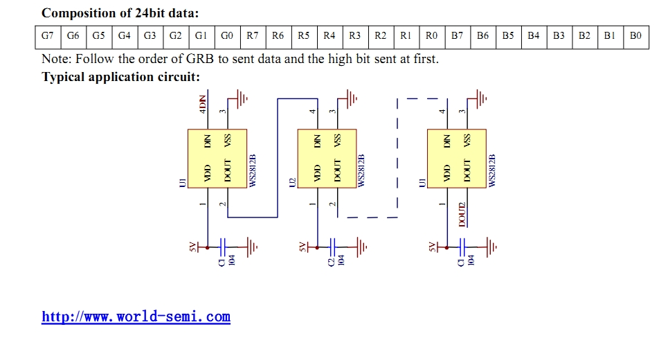
These are "decoupling" or "bypass" capacitors. Their purpose is to stabilize the local supply voltage against fluctuations caused by the interaction of varying current consumption in the circuit with the impedance of the power supply network. "Local" in this case means the supply voltage at each individual LED, which is really an integrated circuit copackaged with red, green, and blue LEDs.
Essentially, every element of the power supply network has some amount of impedance, even down to the individual PCB tracks used to go from one side of the board to the other. The principle aspects of concern here are the resistance and inductance. Assuming that the LED and it's integrated IC consumes a constant amount of current at all times, the local voltage will be perfectly stable, and the only concern is that the resistance of the power supply network is sufficiently low that not too much voltage is lost.
However, real world circuits don't have perfectly stable current consumption--the current consumed will depend on what the device is doing, what sort of signals it's sending or receiving, etc. Digital devices in particular tend to take big gulps of current at every state change. For something like a microcontroller that runs from an internal clock, every clock edge means a very fast current spike.
These spikes in current draw are a problem, because now the inductance of the power supply comes into effect. Inductance is defined, in effect, as a resistance to changes in current, so it makes the power supply network sluggish to respond to the increased current demand. The result is that the voltage at the load (the IC) drops substantially, and in the worst case can "ring", which is when the voltage rapidly fluctuates up and down, which can disrupt or damage the IC. Ringing is a result of overall structure of the power supply network and the position and magnitude of the various parasitic impedances that are an unavoidable fact of electronics in the real world. In extremely fast/sensitive circuits, even the leadframe of the integrated circuit can introduce a measurably significant set of parasitic terms.
Anyway, the solution to the power supply issue is to put capacitors as close as possible to each IC on the board. The key is that there must be as little impedance (most importantly, as little inductance) as possible between the capacitor and the IC's supply pins. Ideally, you would in fact lay out the board so that the power supply current flows 'through' the capacitor's pads and then into the IC, and would not have any vias between the IC and the capacitor. In practice, it's often not possible or feasible to lay out boards that way, and it usually isn't that big of a deal, as long as the capacitor is very close to the IC. Keeping the inductance down means that the capacitor is able to supply the fast gulps of current that the IC needs to operate, and hence stabilizes the supply voltage right at the IC.
So, the short answer to "can I replace a bunch of small bypass capacitors with one larger one?" is "maybe". The longer answer is, it depends on the specific layout of the board (constituent parasitics of the power distribution network, layout of loads), the AC characteristics of the IC in question and other loads on the board, etc. Unless you're prepared to do a lot of analysis on the system, it's easier to simply place several small capacitors. Even if you are prepared to do the analysis, unless your device will be manufactured in the ~millions the cost savings of using one capacitor instead of, say, five, isn't going to outweigh to the cost of the time you spend on that analysis.

