0
\$\begingroup\$

I'm using a Cerwin-Vega CV-2800 audio amplifier to drive the RL circuit depicted in the diagram below:
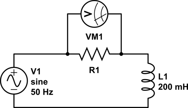
schematic

simulate this circuit – Schematic created using CircuitLab

The amplifier is rated for 1400 W at 2 ohms, 900 W at 4 ohms, and 600 W at 8 ohms. I have two resistors with value 1 ohm and 68 ohms, both rated at 100 W. R1 takes on one of these values. The resistance of the inductor is 40 ohms, and its reactance at 50 Hz is \$2\pi(50)(0.2) =\$ 62 ohms. When R1 is 68 ohms, I see a 3.25 V drop across the resistor; however, when R1 is 1 ohm, I see only a 0.04 V drop.

Questions:

  1. Is this change in voltage because the series circuit divides the voltage across the resistor and the inductor, and the inductor has a much higher impedance than the resistor and therefore drops most of the voltage supplied by the audio amplifier?
  2. Why does the power rating of the amplifier go down as the impedance of the load goes up?
  3. If I wanted to generate a current between 7-10 A amplitude through the RL circuit, is this something my amplifier is capable of? If not, how much power would I need, and is there even such an amplifier out there?
\$\endgroup\$

1 Answer 1

1
\$\begingroup\$

1) this is basic network theory, help us by mentioning the voltage of V1, the 0.04 seems too low, I would expect about double. If the inductor does not behave in a linear way that can explain this.

2) the amplifier behaves as a voltage source, at a given voltage the current decreases as the load impedance increases. As power is voltage times current, a lower current (at a constant voltage) results in a lower power.

To maintain the same maximum power at higher load impedances the maximum output voltage of the amplifier would need to increase. It is possible to make an amplifier capable of doing that but it would be complex and expensive.

3) Figure out how much voltage you would need for that. If you only consider the 40 ohms series resistance then for 7 A you would need 280 V. This amplifier is not going to deliver that much voltage as it is designed for much lower impedance loads.

Where to get an amplifier that can deliver that is a shopping question and off-topic. My bet: if you can find one it will be expensive.

\$\endgroup\$
2
  • 1
    \$\begingroup\$ Remember that the voltage across the inductor and that across the resistor are 90 degrees out of phase. If you measure each amplitude separately, the sum will be more than the input signal. Remember also to take into account your source impedance, or alternatively measure the total voltage for reference. \$\endgroup\$ Commented Aug 28, 2018 at 12:48
  • \$\begingroup\$ Bimpelrekkie and @CristobolPolychronopolis, thanks for your very helpful comments. I followed up with some experiments, and have posted an additional question here: electronics.stackexchange.com/q/394223/176011. Could you please take a look when you get a chance? \$\endgroup\$ Commented Sep 4, 2018 at 2:58

Your Answer

By clicking “Post Your Answer”, you agree to our terms of service and acknowledge you have read our privacy policy.

Not the answer you're looking for? Browse other questions tagged or ask your own question.