1
\$\begingroup\$

Can I enable/disable an LDO (more specifically NCV8163AMX280TBG) by using the I2C SCL signal? This would allow me to turn ON the regulator once a master starts the I2C protocol and turn it off once the master stops communicating via I2C.

If possible, what extra components do I need (caps & diodes probably)?

Any help is appreciated.

PS: The I2C configuration is 1 master to N slaves.

PPS: the regulator turns on at 1.2V and the circuit will be powered from 3.3V

Details: This will be an array of small sensors and actuators built around STM8L001. There will be one STM8L001 for each sensor and actuator. There is a contraint on cost and the number of wires. Currently I have 2 wires for power + 2 wires for communication. When the master wakes up it needs a way to wake up the slaves as well.

I currently see the below options to enable this behaviour:

  • 1 extra wire to drive the ENABLE pin on the LDO from the master (master wakes up, starts i2c, enables the GPIO that starts all the LDOs on the slaves)
  • using MOSFETs to power up/down the entire power rail
  • using the SCL signal to signal the ENABLE pin on the LDO

The sexiest option is the last one as it is the cheapest.

The below schematic is for the slave. As you can see it is a minimal design using STM8L001 with the ENABLE pin directly on the power rail.

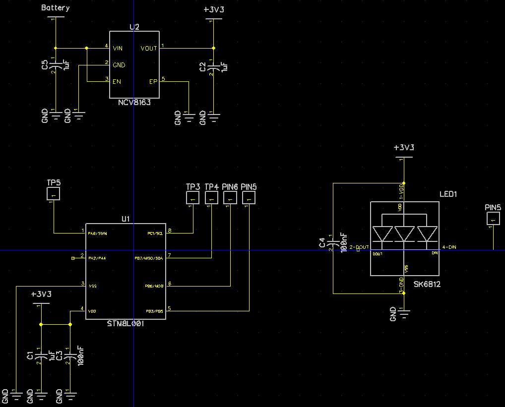
Schematic

\$\endgroup\$
10
  • 1
    \$\begingroup\$ The first transition in an i2c transaction is SDA going low for the START condition. If you wait for an SCL transition to turn on the peripheral, they won't see the START event. \$\endgroup\$
    – The Photon
    Commented Sep 1, 2018 at 16:37
  • 1
    \$\begingroup\$ Adding to @Photons comment, the regulator takes about 120us to turn on, which makes it necessary to send dummy I2C commands to get things started. Why can't you use a DIO pin to enable the regulator? \$\endgroup\$ Commented Sep 1, 2018 at 16:41
  • 2
    \$\begingroup\$ Harder to work around, having an unpowered device on the bus might hold SCL and SDA low. \$\endgroup\$
    – The Photon
    Commented Sep 1, 2018 at 16:55
  • 3
    \$\begingroup\$ smiron - I can think of a way to do this which avoids all of the issues raised in comments so far. However it pushes cost & complexity into other parts of the design. So instead of continuing down this path, let's go back a few steps. This sounds a bit like an XY-problem as you are clearly trying to enable/disable the LDO for some underlying reason, but you haven't disclosed that reason; you also want to use SCL to do that, again for an undisclosed reason. There are other ways, but we don't know why you didn't choose them. \$\endgroup\$
    – SamGibson
    Commented Sep 1, 2018 at 18:07
  • 2
    \$\begingroup\$ [continued] Therefore can you please add more context & background information into the question (e.g. why are you wanting to enable/disable the LDO? Is the power saving so important?) and explain your reasoning for wanting to use SCL (e.g. lack of other GPIO?) Adding a schematic (or at least a block diagram) of your design so far will also help e.g. you can use it to show us where any engineering constraints are, in order to possibly get alternative approaches to solving whatever the underlying problem is. Thanks. \$\endgroup\$
    – SamGibson
    Commented Sep 1, 2018 at 18:13

1 Answer 1

2
\$\begingroup\$

Reusing the SCL for this purpose would enable me to have this behaviour for the lowest cost & complexity.

What?! You need to add some time delay circuit to each slave. Are you saying it would be cheaper and simpler than adding one MOSFET on power rail?

Also, keep in mind that most chips specify maximum I/O voltage relative to VCC. Your I2C pull-ups will feed it to unpowered slaves, pushing them over maximum specified rating. What often happens in this case is that protection diodes pass this voltage to power rails waking up the chip. But since the current is usually insufficient the MCU enters this semi-powered state which sometimes ends up damaging the chip.

The option with one additional wire to EN pins of all LDOs is good solution. The option with one MOSFET to switch power to all slaves is even better solution.

Now, here are couple real solutions.

  • STM8L001 has low power "halt" mode from which it can wake up on interrupts, including I2C interrupts. Furthermore, the I2C module can perform address match and only wake up when this particular slave is addressed. So, you don't have to wake up all of them, only the one you want to communicate with. You don't need any additional components, any additional lines, and the power savings would be probably higher, despite not shutting down the LDOs.

  • Having LDO on each slave is awful overkill. At the distances I2C works power loss in the wires is negligible. So, get rid of all those LDOs. Connect 3.3V power rail with MOSFET. Put I2C pull-ups after MOSFET! When you need to communicate always switch power ON first. Then insert a delay to allow slaves to wake up and configure their I2C. Only then configure and activate master I2C. So, with the cost of 1 MOSFET you can save money on all LDOs, make sure no power is wasted and safeguard I/O pins from high voltage in powered down state.

  • Finally, you can combine the two solutions above for even more savings. Get rid of LDOs and only power up the slaves when you want to communicate. Make each slave configure I2C address and go to sleep immediately after power-up. Then use I2C interrupt to wake one slave at a time. This way there will be zero power consumption between communications and minimal consumption during communication, since only one slave will be awake at a time.

P.S. In the end, @SamGibson was absolutely right to comment about XY problem. For some reason you focused on "sexiest option", ignoring much cheaper and more efficient ones.

\$\endgroup\$
7
  • \$\begingroup\$ you are right in regards to the max IO voltage. I just checked the specs and it is Vdd + 0.3. So this will most likely ruin the chip. Thank you for pointing this out. \$\endgroup\$
    – smiron
    Commented Sep 2, 2018 at 13:06
  • \$\begingroup\$ In regards to removing the LDOs, the same power rail will power a small motor through a motor driver (not sure which one yet). Will this not induce too much noise in the power rail? \$\endgroup\$
    – smiron
    Commented Sep 2, 2018 at 13:08
  • 1
    \$\begingroup\$ The LDO is not a noise filter, especially not at frequencies that motors generate. You have decoupling capacitors for this already in the schematics. Plus there are conventional methods of suppressing motor noise, specifically: two caps between terminals and motor case, another capacitor between terminals, ferrite choke on the power lines next to motor. While I would normally recommend dedicated supply for the motor, in your particular case (and with precautions above) it should be OK, providing your power wires are good for about 1A. \$\endgroup\$
    – Maple
    Commented Sep 2, 2018 at 20:05
  • 1
    \$\begingroup\$ With the above said, are you sure you are not creating another XY problem? Adding LDOs to many I2C slaves only to save 2 power wires for one motor definitely sounds as that. Also, if your motor is supposed to be controlled by I2C commands, why do you need dedicated motor driver at all? STM8L001 timers have PWM support and is more than capable of controlling the motor. All you need is H-bridge and primitive PWM code with I2C commands. \$\endgroup\$
    – Maple
    Commented Sep 2, 2018 at 20:31
  • 1
    \$\begingroup\$ C1, C3 and C4 are the caps I was referring to. That's more than enough decoupling for I2C slaves. You do need big capacitor at the power source, of course. And another one on the motor driving module before the H-bridge, something in 50~200uF range, depending on PWM frequency. These big caps are not for noise filtering but for keeping power stable when slaves wake-up or motor starts running. Other than that (and with appropriate noise filtering on the motor, as I mentioned earlier) you should be good to go. \$\endgroup\$
    – Maple
    Commented Sep 2, 2018 at 23:41

Your Answer

By clicking “Post Your Answer”, you agree to our terms of service and acknowledge you have read our privacy policy.

Not the answer you're looking for? Browse other questions tagged or ask your own question.