3
\$\begingroup\$

enter image description here

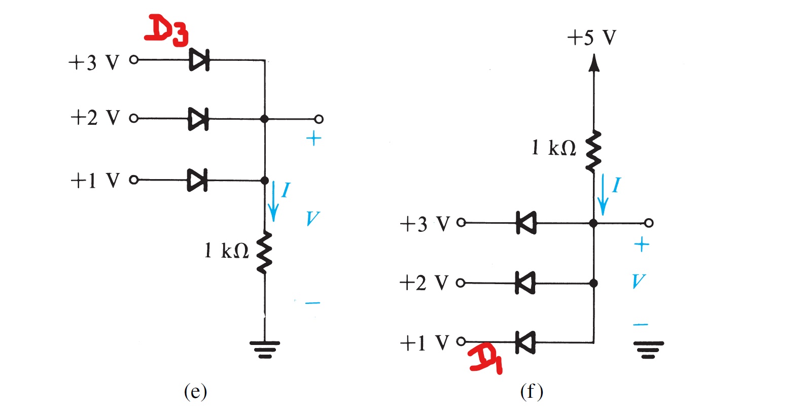
Given:"all the diodes are ideal",in figure (e), only D3 is on and rest of the two diodes are given off in the solution. Similarly for (f) only D1 is on. I don't understand the logic behind this. Please help in understanding this thing.

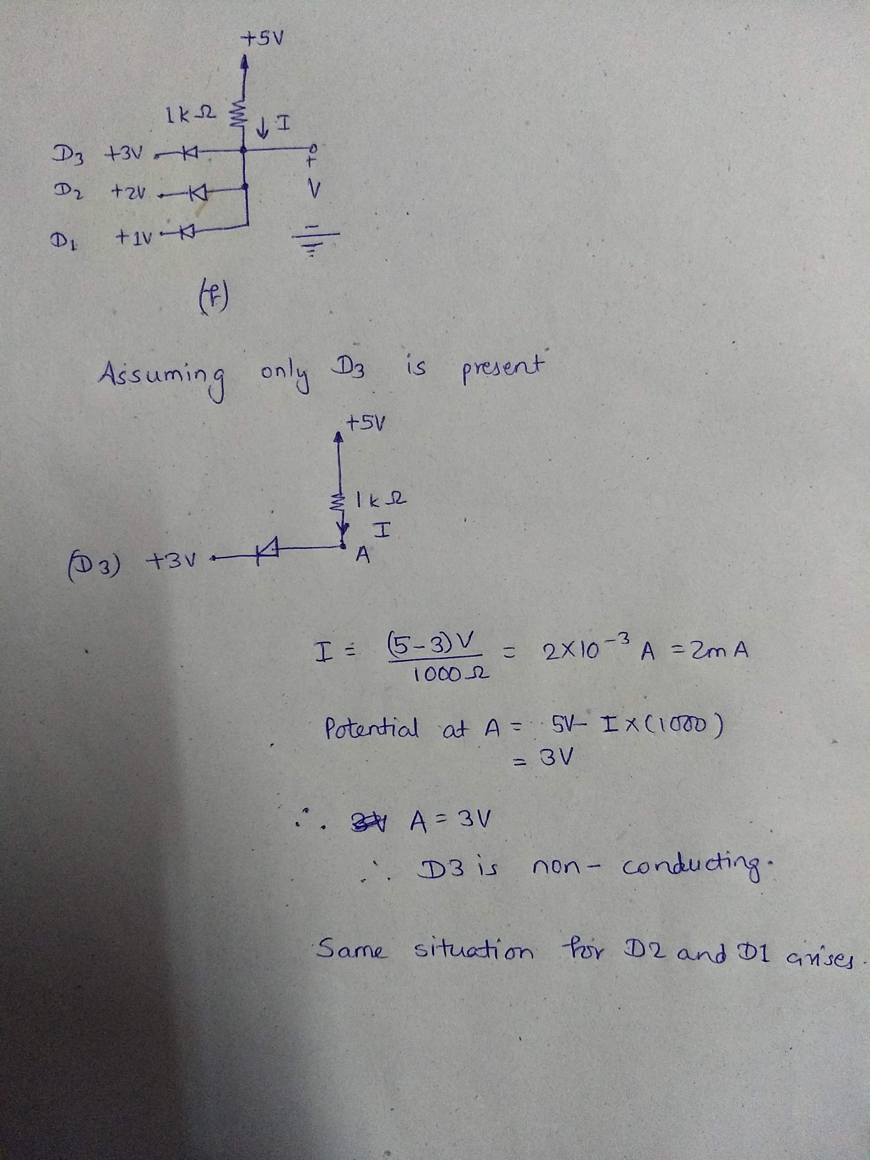
Update: Showing my work for (f)

Assuming only D3(diode with 3V) is present and is in "on" condition.I end up getting same situation if I begin with D1 or D2, which gives all diodes are off.my work for (f)

\$\endgroup\$
0

3 Answers 3

5
\$\begingroup\$

One way to arrive at the solution is to think of each diode individually. What would the voltage be at the output if only one diode is present? Assuming 0.5V drop for a diode, in (e) it woudld be 2.5V with only D3, 1.5V with only D2, 0.5V with only D1. (Assuming the diodes are numbed from the top to bottom). Can you see how to determine these voltages?

Now, in each situation, add the other diodes, one by one, and see whether it would influence the situation.

Starting with only D3, if we add D2, it would be blocking, because its left side has a lower voltage than its right side. Same for D1. Hence this situation (2.5 at the output) is consistent.

Starting with only D2, if we add D3 nothing happens. But if we add D1 we have a problem: its left side is 3V, right side 1.5V. That is not consistent with normal diode behaviour (should be 0.5V drop, but we have 1.5V in this situation). Hence this assumption (1.5V at the output) is invalid.

Same reasoning rules out the 0.5V at the output situation.

So we have only one consitent solution: 2.5V at the output, D3 conduction, D1 & D2 blocking.

You can use the same line of reasoning for (f).
\$\endgroup\$
5
  • 1
    \$\begingroup\$ I tried same way for f but didn't get to solution. Please help \$\endgroup\$
    – Sahil
    Commented Sep 2, 2018 at 16:22
  • 2
    \$\begingroup\$ @Nature: Then edit your question showing your work for (f) so we can see what the problem is. \$\endgroup\$
    – Transistor
    Commented Sep 2, 2018 at 16:51
  • \$\begingroup\$ @Transistor: I have updated my question showing my work.Sorry for late reply, I was late night yesterday. \$\endgroup\$
    – Sahil
    Commented Sep 3, 2018 at 0:34
  • \$\begingroup\$ @Woutervanooijen: "Starting with only D2, if we add D3 nothing happens." I thought while adding D3(before D2 was only present), D3 would now block D2 becuase D2 would have lower potential on left. Can I get to the conclusion(D2 remains off) this way? \$\endgroup\$
    – Sahil
    Commented Sep 3, 2018 at 1:24
  • \$\begingroup\$ @Nature in your initial calculation, you assumed 0V drop over the (conducting) diode. If that assumption is valid (depends on what your've been taught) a diode with 3V at both sides is conducting. Personally I'd prefer to assume a drop voltage. 0.6V is often used, in my answer I used 0.5V for easier calculations. \$\endgroup\$ Commented Sep 3, 2018 at 6:17
2
\$\begingroup\$

Regarding your edit, and the right half of your original image:

Assume the voltage drop across D3 is 0.7 V. With your drawing, where only D3 exists, the voltage at A would be 3.7 V.

Now add D2. D2 would turn on (start conducting) and would pull the 3.7 V at A down to 2.7 V, turning off D3.

Now add D1, which would turn on and pull A down to 1.7 turning D2 off.

So now, at only 1.7 V, the only diode which can conduct is D1.

\$\endgroup\$
1
  • \$\begingroup\$ @Nature As to why the voltage is pulled down when you add a diode, I would suggest looking up “diode forward voltage”. This link looks pretty good. \$\endgroup\$ Commented Sep 3, 2018 at 15:04
0
\$\begingroup\$

There is a fault in your logic in your update (the photo of your solution).

You have assumed that only D3 is present and then worked out the current through it on the correct basis that the voltage at the junction is 3 V.

Now you make your mistake:

A = 3 V, therefore D3 is not conducting.

But you started by stating is is conducting. If D3 is not conducting then A would be +5 V because no current is flowing. D3 is conducting.

In real diodes there would be a voltage drop across them - usually 0.7 V - so 'A' would be at 3.7 V and the diode would clearly be forward biased.

\$\endgroup\$
0

Your Answer

By clicking “Post Your Answer”, you agree to our terms of service and acknowledge you have read our privacy policy.

Not the answer you're looking for? Browse other questions tagged or ask your own question.