2
\$\begingroup\$

I need to design a breakout board for this Cree XHP50 LED. It is a 12V LED that I would like to run at 1.5A.

It will be turned on by this ON Semi NSS12201LT1G NPN transistor, which is connected to a 12V power source and an ESP32. I will use PWM on the ESP32 in order to slowly dim the light in and out over the course of 30 minutes.

I am concerned about a couple things and would really appreciate any help.

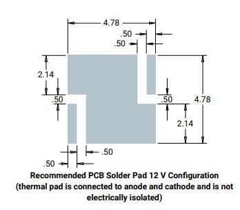
SMD Pad

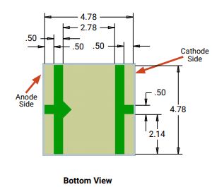
Here is the pad required for the LED. However, I don't understand how to wire this up to the 12V power source. Do I run a VCC trace to bottom left and GND to the upper right? Won't the thermal pad cause a short?

Solder Pad Bottom View

Heat Dissipation

Is it a bad idea to place this on a small 2 layer breakout board? I plan on making a ground plane on both layers, but is this still a bad idea without a heatsink or aluminum PCB?

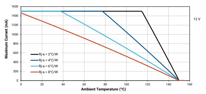
I don't understand what Rj-a means at why there are different temperatures for different lines.

Thermal

Thank you so much for your time.

\$\endgroup\$
3
  • \$\begingroup\$ Do you think your PCB would successfully dissipate 18W at some reasonable temperature? Anything above 45-50degC cannot be touched, and above 70degC may result in a burn. \$\endgroup\$ Commented Sep 10, 2018 at 16:18
  • \$\begingroup\$ @JackCreasey That's a great question. Unfortunately I do not know how to figure that out without building, testing, and adjusting the current \$\endgroup\$ Commented Sep 10, 2018 at 18:30
  • \$\begingroup\$ There exist tables of Copper clad & MCPCB thermal resistance. My answer gives some clues. Both parts in your design are at great risk of burning fingers let alone the parts. \$\endgroup\$
    – D.A.S.
    Commented Sep 10, 2018 at 20:02

5 Answers 5

2
\$\begingroup\$

Why did you select this LED. It is designed for a very specialized product, one that need a lot of lumens in a small space like a spot light or street light.

You do not have to dissipate all of the 18.375 watts (12.25V @ 1.5 A) because about 45% of the electrical power is dissipated in radiant watts (light) leaving only 55% of the electrical power to be dissipated as thermal watts (heat).

BTW you cannot run these at 12V and 1.5A. The typical Vf is 12V @ 1200 mA.

Is it a bad idea to place this on a small 2 layer breakout board? I plan on making a ground plane on both layers, but is this still a bad idea without a heatsink or aluminum PCB?

Yes, it is a very bad idea to use a small PCB with no heatsink.
You cannot reasonably dissipate 9 watts using the PCB surface. A small PCB with a heatsink is more cost effective.

This is a small PCB populated with Luxeon Rebel LEDs that each dissipate 1.5 Watts of heat. The PCB has backside copper and thermal vias. LEDs are spaced 0.75" apart on a 0.7" wide strip.
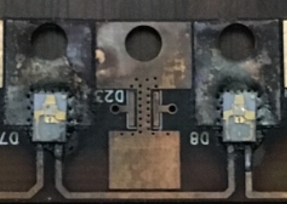
enter image description here

This LED required to be cooled with a water cooled heatsink with a sufficient volume of water per minute.

Here I attached the PCB to a copper bar and attached the bar to a copper water pipe. This was actually an inexpensive heat sink with a materials cost of about $3 per foot. Drilling the holes and mounting the copper bar was labor intensive.

I attached the bar to the LED side of the PCB to avoid inefficient thermal vias.
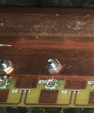
enter image description here

I used two (in case one failed) small (1 gal/minute) submersible water pumps
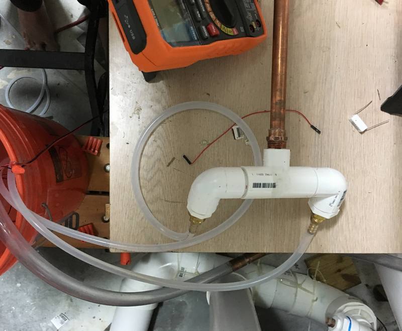
enter image description hereenter image description here


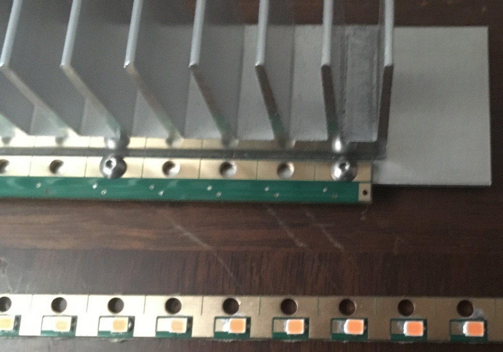
This is the best passive design used to cool a small PCB was a strip that is 9 mm (0.35") wide.

A 0.062" thick aluminum strip which is 1.35" wide mounted to the LED side heat spreading copper. The LEDs face down and the fins face upward. This can also be used when the LEDs and fins are facing sideways.

This 1" x 12" heatsink costs $5.
enter image description here

I would suggest using a lower powered LED and spread out the LEDs if possible. Lower power LEDs are more efficient where they can dissipate up to 80% of the electrical power as radiant watts.

A mid powered Samsung LM301B is almost twice as efficient as this Cree XHP50.

The most efficient high powered LED is the Cree XP-G3 but not as efficient as the mid powered LM301B which is the most efficient white LED.

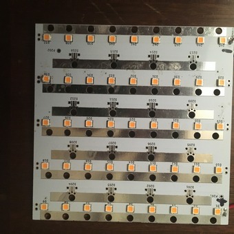
The LM301Bs do not need a heatsink when driven at full power (200 mA) on a 1" wide strip.


This PCB is 100 mm x 100mm with 45 mid power LEDs which provides 1,700 lumens at 65 mA each. This board uses a total of 8 electrical watts and generates a total of about 2 thermal watts. No heatsink required.
enter image description here


It's about real estate. Do you really need to cram all those lumens in to a tiny area?

The pros mostly use mid power LEDs when making light bulbs:

enter image description here
watts are wall watts

\$\endgroup\$
1
\$\begingroup\$

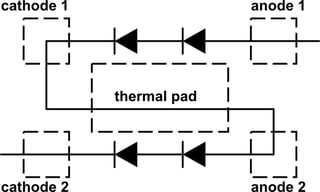
The package for this LED consists of two isolated strings of two LEDs each. In the "recommended PCB solder pad 12 V configuration", the two strings are being wired in series through the thermal pad, as seen in the diagram below. The top and bottom pairs of anode and cathode pins are not internally connected to each other, so there is no "short" created by the recommended layout.

Refer to page 32 of the datasheet for details.

schematic

simulate this circuit – Schematic created using CircuitLab

\$\endgroup\$
0
\$\begingroup\$

To address the second part of the second section of your question:

\$R_{j-a}\$ is the thermal resistance from Junction to Ambient.

The different lines are the de-rating curves for different total thermal resistances - as you put better heat-sinking (lower \$R_{j-a}\$) on your LED, you can run your LED in a higher ambient temperature before you need to reduce the maximum current you push through it.

\$\endgroup\$
0
\$\begingroup\$

I would go with the bottom pad on page 31, and use vias to help conduct heat from the 8 ground pads to a large ground pad under the part (opposite side of the board). Also use a ground pad around the part to help with heat dissipation.

Look at the ON characteristics of that transistor - everything is in mA. That part will burn up at 1.5A.

Instead, use a low Rds, logic level, N-channel MOSFET, such as AOD510 or AOD514 from Digikey

https://www.digikey.com/products/en/discrete-semiconductor-products/transistors-fets-mosfets-single/278?k=aod5&k=&pkeyword=aod5&sf=0&FV=ffe00116&quantity=&ColumnSort=0&page=1&stock=1&pageSize=25

\$\endgroup\$
2
  • \$\begingroup\$ Thank you, I see exactly what you mean. Do you know why they recommend connecting the thermal pad to the cathode and anode? I just can't figure that part out. \$\endgroup\$ Commented Sep 10, 2018 at 17:55
  • \$\begingroup\$ You can do that for cooling as well, but you need to keep those pads isolated then, not connected to the ground plane. \$\endgroup\$
    – CrossRoads
    Commented Sep 10, 2018 at 19:05
0
\$\begingroup\$

This LED that the Op has chosen can be driven at 30% duty cycle on my design example below at 3 Amps for an ambulance on MCPCB with acceptable heat rise. Viewing angle @50% is 120 deg instead of 160 deg Lambertian. So it makes a good flood light or wide-angle view with some 50% gain in the lens or a spot light at close range.

enter image description here

\$R_{ja}=R_{jc}+R_{ca}\$ for heatsink thermal resistance \$R_{ca}\$

My Rule of thumb for LED's is to allow 100 cm²/W per Watt Pd on PCB copper heat spread and 10 cm²/W for MCPCB.

But the heat emitter surface area makes a big difference especially SOT23 which require more area, depending on Rce, which I explain later.

But you must define Case temp rise for a good design and Ta max for internal ambient, like <30'C rise at 30'C or <20'C rise @ 40'C to determine max LED current and Rca spec. Otherwise higher T "may" be acceptable but compromises design quality.

Add-on 2'C/W Heatsink is better for more surface area.
MCPCB may be more cost-effective than large addon heatsink depending on what case you have which can (negatively affect Rja) insulate ambient cooling.

The transistor choice may be poor since Rce(sat) = 0.085V_ce/1.4A_ce= 60 mΩ (max) with 0.14A_be . (Ic/Ib=10 for opt. Vsat and =Ic/Ib=100 raises Rce to 80 mΩ

thus I²Rce= 1.4² 80 mA= 157 mW , Ra= FR−4 @ 100 mm² , 1 oz. copper traces. NPN Rja 270'C/W so T rise= 270 * .157W = 42'C rise with 100mm² copper heat spread.
Rce or RdsOn of driver 10mΩ is 10/60 Ω so the copper area can be reduced to 100/6= 17mm².

Anecdotal

I tend to re-use designs. Using a bandsaw I cut large arrays into strip from an array of LEDs on Alum-clad PCB used for Ambulances in Canada. Notice the double-sided area per LED. The surface has an epoxy coating over copper tracks which does not affect the thermal resistance. However, FR4 is a thick thermal and electrical insulator. Power them on long cables is easy since the Ri of each pulsed 3W LED is <300 mOhms so wire resistance allows parallel operation from near equal drop voltage with AWG 16 household wire distribution around the fence. Strip LEDs are easier to install but far less right so these are local 1~2m spotlights. Inverted mounting to a cedar cover hides the light source. Since no addition heatsink was used, I used conservative currents for 1W per LED.(<300mA) and they are only warm to touch with free convection air which makes a difference. ( most ceilings LED chip lights would burn your finger if you could touch them due to lack of forced air or free airflow over the heatsink.)

I use them for hidden luminaires around the garden and are very bright with 0.5 to 1A. I use a variable voltage SMPS dimmer. The Epoxy is easily removed with an Exacto knife and soldered with magnet wire then a dab of Polyurethane for a strain relief and solder environmental protection outdoors. I got over 2K LEDs on large array boards almost free $10 from a scrap aluminium shop. About 0.1% of the LEDs were "almost bad" ( lower intensity on one of 48). These were sold as scrap. They got them from a local board shop. So ... go around scrap metal shops in major cities and tell them you will buy future scrap with these funny looking bad LEDs. These have plastic lens for beam narrowing for ambulence visibility but they make great spot lights.

\$\endgroup\$
9

Your Answer

By clicking “Post Your Answer”, you agree to our terms of service and acknowledge you have read our privacy policy.

Not the answer you're looking for? Browse other questions tagged or ask your own question.