0
\$\begingroup\$

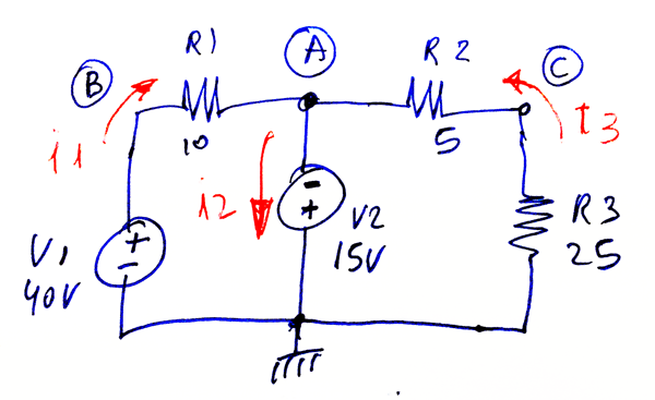
I am trying to do a nodal analysis of this circuit.

enter image description here

and I need to do this by nodal analysis only.

I need to find \$ i_1 \$, \$ i_2 \$ and \$ i_3 \$.

I have found that

\$ i_1 = \frac{V_B - V_A}{R_1} = \frac{40 - (-15)}{10} = \frac{55}{10} = 5.5 A \$

\$ i_3 = \frac{V_A}{R_2 + R_3} = \frac{-15}{5 + 25} = \frac{-15}{30} = -0.5 A \$

Both these value are correct, according to the simulator.

But this is the problem:

\$ i_2 = i_1 + i_3 = 5.5 + (-0.5) = 5 A \$

But the simulator says -6A.

What is the correct way to approach that?

\$\endgroup\$
7
  • \$\begingroup\$ ??? please explain better. \$\endgroup\$
    – Duck
    Commented Sep 14, 2018 at 16:30
  • \$\begingroup\$ sorry about that. It was a typo. Simulator shows -6A. SEE HERE \$\endgroup\$
    – Duck
    Commented Sep 14, 2018 at 16:34
  • \$\begingroup\$ My simulator says -6A as well (using LTSpice). However, I believe it's measuring the current going into Node A, hence why it's -6A. \$\endgroup\$
    – user103380
    Commented Sep 14, 2018 at 16:51
  • 1
    \$\begingroup\$ i3=0.5A........ \$\endgroup\$
    – Chu
    Commented Sep 14, 2018 at 17:21
  • 1
    \$\begingroup\$ @KingDuken, i3=0.5A with the current direction the OP has specified. \$\endgroup\$
    – Chu
    Commented Sep 14, 2018 at 19:55

2 Answers 2

3
\$\begingroup\$

I checked with my simulator as well with LTSpice and I got the same result of -6A. I believe your simulator is trying to read the current that is going into your assigned Node A from your picture, which is why the current is negative. Current going into a node is always negative.

As far as your math goes, it's not entirely correct. Because the direction of \$i_1\$ and \$i_2\$ is going in a clockwise direction, your sign for \$i_3\$ is actually going to be negative because it's traveling counterclockwise.

Hence \$i_2=i_1-i_3=5.5A-(-0.5A)=6A\$, which makes sense because you have \$i_2\$ leaving the node and thus being positive. However, if you had \$i_3\$ going in the clockwise direction, it would be \$i_2=i_1+i_3=5.5A+0.5A=6A\$...

And I know what you're thinking...

Even if \$i_3\$ was going clockwise, how would I get a negative current reading?

If you let \$i_3\$ go into the clockwise direction, it would actually be \$\displaystyle i_3=\frac{15}{30}\$ because the current is going into the positive terminal of the voltage source.

So in conclusion: Your math was incorrect and your simulator was measuring the current going into your Node A from your picture.

Lovely tip for next time: Make sure your current conventions are all the same. Don't have one current going clockwise and another going counterclockwise. This will confuse you and it's going to mess up your math.

\$\endgroup\$
5
  • \$\begingroup\$ You are right, the simulator is measuring the current going into A. To confirm that, I have added a very little resistor (0.0001 Ω) in series with V2 and measured the current on that resistor. It says +6A!!! Thanks. This was killing me! \$\endgroup\$
    – Duck
    Commented Sep 14, 2018 at 17:36
  • \$\begingroup\$ what I do not understand is why such simulators would measure current going up in that case.... anyway, thanks. \$\endgroup\$
    – Duck
    Commented Sep 14, 2018 at 17:45
  • \$\begingroup\$ I actually don't know... LTSpice was doing that as well when I did the simulation there. I think it didn't want to measure current that was going to ground. \$\endgroup\$
    – user103380
    Commented Sep 14, 2018 at 17:57
  • \$\begingroup\$ @SpaceDog and KingDuken, I don't understand your perplexities: the simulator reports the currents crossing devices (it doesn't care about nodes) according to certain reference directions chosen conventionally. For voltage sources, Spice chooses the reference direction for the current from the + terminal to the - one. Therefore, if in the simulation you looked at the current I(V2), the sign is negative because the current actually crosses the voltage source from terminal - to +. \$\endgroup\$ Commented Sep 14, 2018 at 19:49
  • \$\begingroup\$ @SpaceDog note also that by adding the small resistor in series to the voltage source, you obtained the "right" sign by chance: if you mirror the resistor upside-down (press twice Ctrl+R), you'll get a negative value again. \$\endgroup\$ Commented Sep 14, 2018 at 19:49
0
\$\begingroup\$

The voltage at Node A is \$\small-15V\$, hence \$\small i_1=\frac{55}{10}=5.5A\$, and \$\small i_3=\frac{15}{30}=0.5A\$. Currents at Node A: \$\small i_1+ i_3=i_2=5.5+0.5=6A\$.

\$\endgroup\$

Your Answer

By clicking “Post Your Answer”, you agree to our terms of service and acknowledge you have read our privacy policy.

Not the answer you're looking for? Browse other questions tagged or ask your own question.