0
\$\begingroup\$

This is a follow up question to this:

Alternatives to Large Transformer or PSU for Driving DC Heater

I've hooked up 120v AC to a zero crossing SSR and a 3.2 ohm resistive load. To get my desired wattage I send trigger pulses the the SSR periodically to create a 10% duty cycle.

This is working fine, but as I expected it's causing the lights in my workshop to flicker.

What's the simplest way to prevent this? I would like to use as few "large" components as possible.

Here're my ideas:

  1. Use an inductor to limit the peak current to a more reasonable level.

  2. Rectify the AC, then feed that into a large 200v cap. Then Draw from that using a DC SSR.

Update:

I've switched to a 1000W electric cooktop with a much more reasonable peak current. This also flickers the lights every time it switches on and off, although that's once per 5 seconds now instead of 4 times per second. I guess Spehro was right I just need better lights...

\$\endgroup\$
5
  • 1
    \$\begingroup\$ ten percent duty-cycle for what frequency of operation? Note: I'm not asking here about mains @50/60 Hz. For lighting, this scheme not works - high flickering (for thermal loads yes). \$\endgroup\$ Commented Sep 14, 2018 at 21:09
  • \$\begingroup\$ The SSR is zero crossing, so I can only switch half waves from the AC. That makes the frequency 120hz. I switch on the SSR for one half wave at a time at regular intervals (verified via oscilloscope). \$\endgroup\$
    – Drew
    Commented Sep 14, 2018 at 21:16
  • 1
    \$\begingroup\$ Have you considered replacing the lights with ones that are less sensitive to line voltage variations? \$\endgroup\$ Commented Sep 14, 2018 at 22:45
  • \$\begingroup\$ This question does not relate to reflow in any way I can see. Did you mean rework or modification? \$\endgroup\$
    – K H
    Commented Sep 15, 2018 at 0:09
  • \$\begingroup\$ KH, It's for a reflow soldering plate I'm building. \$\endgroup\$
    – Drew
    Commented Sep 15, 2018 at 4:27

1 Answer 1

2
\$\begingroup\$

\$ I = \frac {V}{R} = \frac {120}{3.2} \approx 40 \ \text A \$ so it's no wonder that your lights flicker.

  1. The inductor will cause the current to ramp up slowly but will also cause it to run on after zero cross so this will present itself as a problematic load.
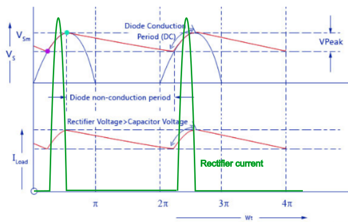
  2. Option 2 could work but the capacitor has to get recharged on each mains half cycle and you would get large pulses of current for a brief while after the input voltage exceeds the capacitor voltage.

enter image description here

Figure 1. This image I had prepared for a half-wave rectifier question gives some idea of the problem. Large pulses of current are required to top-up the rectifier on each half-cycle so you would have twice as many pulses.

Another option is to series connect a reactive component with the mains. Your linked question says you require about 500 W into 3.2 Ω so you need \$ V = \sqrt {PR} = \sqrt {500 \times 3.2} = \sqrt {1600} = 40 \ \text V \$ across the resistor. The reactive component will have to drop \$ \sqrt {120^2 - 40^2} = 113 \ \text V\$ at \$ I = \frac {V}{R} = \frac {40}{3.2} = 12.5 \ \text A \$.

The reactive impedance required is \$ Z = \frac {V}{I} = \frac {113}{12.5} = 9.04 \ Ω \$

At 60 Hz we get

  • \$ C = \frac {1}{2 \pi f Z_C} = 300 \ \mu \text F\$

or

  • \$ L = \frac {Z_L}{2 \pi f} = 24 \ \text {mH}\$.

Theoretically, either of these, rated at 12.5 A, 60 Hz, should work.

\$\endgroup\$

Your Answer

By clicking “Post Your Answer”, you agree to our terms of service and acknowledge you have read our privacy policy.

Not the answer you're looking for? Browse other questions tagged or ask your own question.