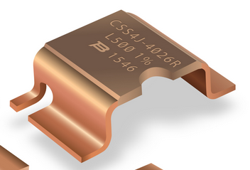
I am using a 10 mohm 1% shunt to measure current via voltage drop.
My circuit is on a breadboard...
It behaves as if the shunt has a value of ~30-40 mohm instead of 10 mohms. I double checked this by sourcing the current through the shunt alone and reading the voltage drop. I am pretty sure the source of this extra resistance is from the contact connections to the shunt.
Right now the breadboard circuit is trimmed for a ~30-40 mohm shunt value. My question is should expect to see the correct 10 mohm value when everything solder to a PCB? If so I need to change up the part selection and PCB component labels.
However, if I should be seeing minimal added resistance from the breadboard connections this could mean they sent me the wrong shunt value or it's defective. I only have 1 unfortunately so I can't verify if it's behaving unexpectedly.
Here are some pictures:
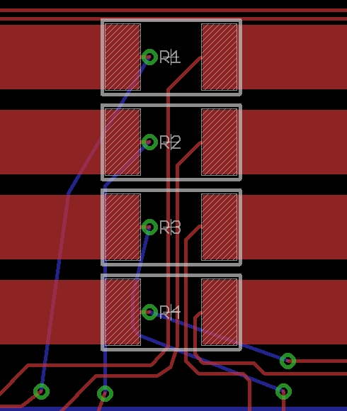
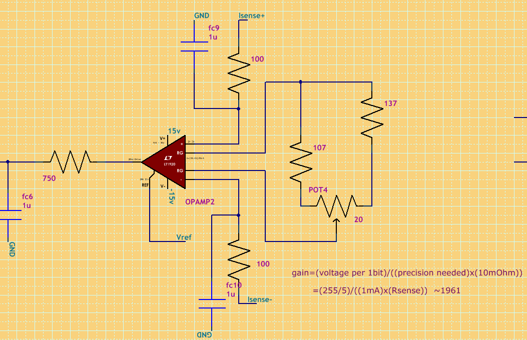
Schematic, Isense+/- connect to the shunt resistor.
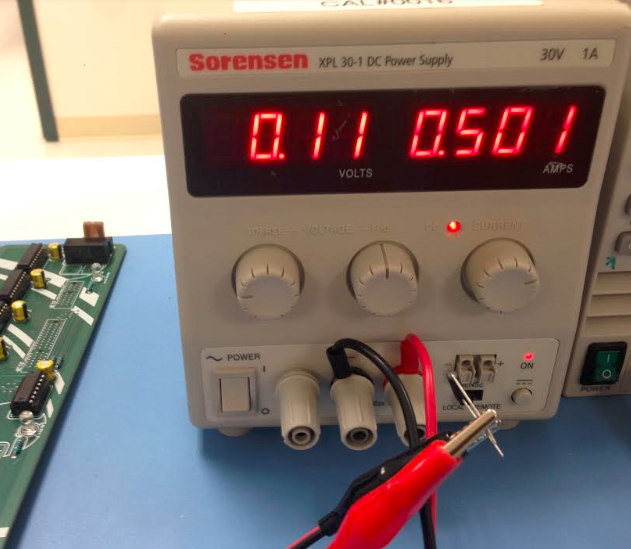
Resistance measurement with meter. This is showing 220mOhm, depending on what connectors I use I typical get ~40-50mOhms... the point is its definitely not 10mOhms:
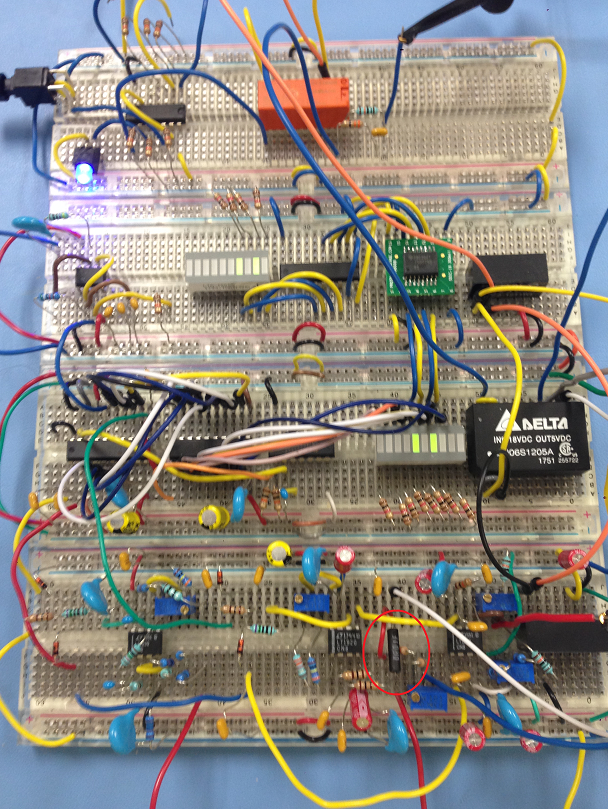
Here's the breadboard bird nest. It's tuned for ~30mOhm shunt. Works accurately and consistently.
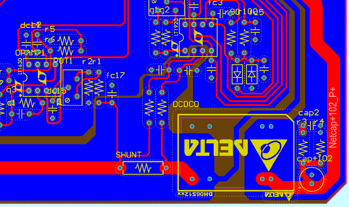
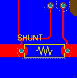
Here is the proposed PCB layout. The different ground planes are connected at a star so don't worry about that; I found it was the cleanest way to do it, I don't want to get into a ground plane argument...
