0
\$\begingroup\$

A general question:

Lets say I have a square wave signal from 0 to 5 volts. What I would like to do is create a circuit that will convert this 0 to 5-volt signal to a -2.5V to +2.5V for example. ( remove the dc )

I do NOT want to have a negative voltage reference for the -2.5V in my circuit. What options do you think can create this kind of circuit? (for example, high pass filter maybe with Schmitt trigger? Other options? )
My square wave is at 200kHz and 50% duty cycle.

More info:

The square wave signal drives a transformer and after the transformer, a diode and a capacitor rectify the signal in order to create a DC output.

What I want to build, is a floating voltage that can be controlled by the frequency of my square wave. I need to connect this voltage in another circuit so that is why I use the transformer, for isolation and not having a ground reference on the secondary side.

The above question that I have is more general, in order to understand about level shifting.

In my case:
My AC waveform that I power on the primary side, can be a square wave or sine wave (I am not sure what is the best). The current that I need on the secondary side is about 1A. My transformer is a 1:0.8 (primary:secondary) and the voltage on the secondary side that I need, is about 10-12 volts and this voltage should be adjustable by the frequency or amplitude of the primary side's AC waveform.

Thanks a lot.

\$\endgroup\$
24
  • 2
    \$\begingroup\$ Yes, a capacitor-coupling to a +2.5V DC with a diode clamp gets you there. But this PWM signal will drive something. Would be helpful if you included the end-use of the desired +2.5/-2.5 PWM signal. What load will it see? \$\endgroup\$
    – glen_geek
    Commented Sep 29, 2018 at 18:35
  • \$\begingroup\$ Hi thanks for your response. I would like to drive this pwm signal in a transformer.Do you think that I have to use any other circuit after that? In addition can you send a photo of the circuit that you mean. What type of diode, which topology? Thanks \$\endgroup\$
    – George A
    Commented Sep 29, 2018 at 18:38
  • 1
    \$\begingroup\$ BUt FLux walk is a real issue, Either you monitor current and regulate for balanced currents or choose a topology that prevents DC flux walking and core saturation. \$\endgroup\$
    – D.A.S.
    Commented Sep 29, 2018 at 19:08
  • 2
    \$\begingroup\$ You should clarify what you want to do...shifting a PWM signal from 0/5V to +/-2.5V is the same as removing the dc component only when the duty cycle is 50%. \$\endgroup\$ Commented Sep 29, 2018 at 19:08
  • 1
    \$\begingroup\$ @George: You have 11 comments so far trying to figure out what you are asking. That means your question is very unclear. Your edit makes it worse because you are taking a 0 - 5 V signal, trying to get it through a transformer to rectify it to generate a DC signal again. Why? Why not just filter the original signal to generate the DC? What are you trying to make? A constant 50% PWM signal doesn't change so you might as well just use a DC power supply. \$\endgroup\$
    – Transistor
    Commented Sep 29, 2018 at 19:58

3 Answers 3

1
\$\begingroup\$

You apparently want to drive a transformer primary with a 5 V square wave, and what you have goes from 0 V to 5 V.

First, check whether this is even a problem at all. How much current will the transformer draw with 2.5 V DC input? Would 5 V DC input saturate the core or not. If the average DC current is acceptable and the core won't saturate, then you don't need to do anything.

Otherwise, put a capacitor in series.

However, you have bigger problems since you don't seem to understand transformers and you specs don't make sense:

My transformer is a 1:0.8 (primary:secondary) and the voltage on the secondary side that I need, is about 10-12 volts

This won't work. With a 5 V square wave in and a 1 to 0.8 ratio, you will get a 4 V square wave out.

I you want 10 V out, you need a transformer with more than 1:2 ratio. 1:2 will give you 10 V out unloaded. You need a bit more to compensate for the loss in the transformer, and the diode drop in rectifying the output.

Overall, you need to step back and figure out what you really want. Your question makes no sense as currently written.

\$\endgroup\$
1
  • \$\begingroup\$ Thanks for the response. I totally agree with your comment. My question was more general. For sure in my case, I will need a biggerer than 1:0.8 ratio in order to obtain the 10-12v. \$\endgroup\$
    – George A
    Commented Sep 30, 2018 at 13:33
0
\$\begingroup\$

Ok, it seems to me that you want to build some kind of power transfer circuit. Your input signal is not called PWM, because it has a fixed 50% duty cycle.

Concerning your question, you want to shift your original 0/5V (mean 2.5Vdc) signal to -2.5/+2.5 (mean 0Vdc) voltage level.

You can do this with a simple series capacitor. The output terminal of the capacitor is undefined concerning the DC operating point and thus can be tied to GND (or any other voltage level) with a (high impedance) resistor.

For driving the transformer with a low impedance driver, you might want to add a voltage follower stage.

\$\endgroup\$
2
  • \$\begingroup\$ What you say is creating a high pass filter with a capacitor and resistor? Thanks \$\endgroup\$
    – George A
    Commented Sep 30, 2018 at 8:21
  • \$\begingroup\$ Yes, that’s a simple first order passive high Pass filter. \$\endgroup\$ Commented Sep 30, 2018 at 14:41
0
\$\begingroup\$

How can you say PWM and not care about PW. Are you aware of flux walk thermal runaway?
– My Comment 18 hours ago

Generally, transformers for SMPS fall into 3 categories;

1) Flyback for <150W using Volt-sec [V-s] charge discharge products with deadtime T>L/R - equal Vs time product to prevent current integration towards core saturation. - Basic law V * dt = L*dI, Imax=V/R(loop)
2) Single half bridge primary center-tap to V+ with more linear transformer characteristics but still has dead time to prevent flux walk (most common on ATX supplies)
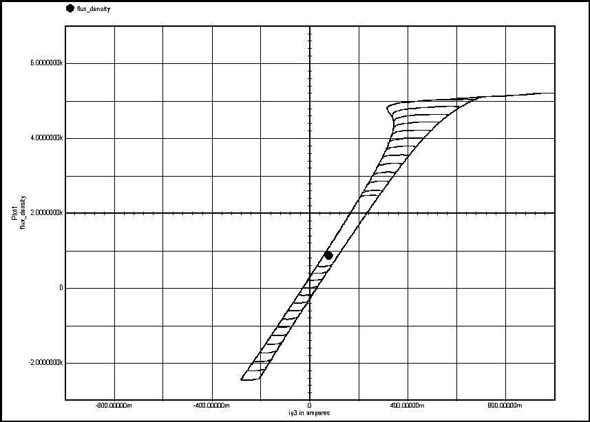
3) Dual half-bridge drivers to each supply rail to untapped primary with a dual half bridge on each primary end and deadtime as above. enter image description here Ref When a core average current has a DC component, it integrates the B flux to one end or the other. Remanence or magnet B field memory after power off also stores energy like a cap* with voltage and saturation is the 10% drop in inductance before it becomes a flat line ( zero inductance) and the coil now is just a resistor low DCR causing thermal runaway in the driver and core. (failure)

This* is similar to a cap going over voltage into dielectric breakdown into a short circuit.

\$\endgroup\$

Your Answer

By clicking “Post Your Answer”, you agree to our terms of service and acknowledge you have read our privacy policy.

Not the answer you're looking for? Browse other questions tagged or ask your own question.