So assuming it's a simple oscillator like so :

How can I start this oscillating with an initial value then make sure this value doesn't affect the operation of the circuit?
So assuming it's a simple oscillator like so :

How can I start this oscillating with an initial value then make sure this value doesn't affect the operation of the circuit?
Not only can you do this, you can synchronize the start of oscillations quite precisely.
EDIT - Not only can you start the oscillator precisely, this topology will produce a complete last pulse. Simpler on-off configurations may produce narrow last pulses if the off condition occurs during a pulse, but not this one. END EDIT
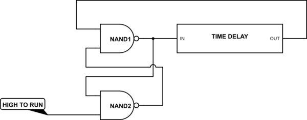
Start with this structure

simulate this circuit – Schematic created using CircuitLab
A low input will inhibit oscillation, and when the input goes high oscillation will start.
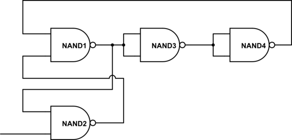
As for the time delay, assuming you're using discrete logic, you can take advantage of the common occurrence of quad NAND gate ICs by implementing

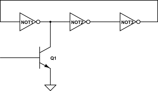
Of course, you can also use a couple (or 4 or 6 or ...) of inverters to do the job.
Alternatively, you can simply brute-force the issue. Using an open-collector output or a separate transistor, you can

This takes into account that every (discrete, at least) logic family on the market will tolerate a short circuit to ground indefinitely. If it could not, you'd get any number of dead ICs due to inadvertant shorts during test, assembly or use. This approach will cause a slight change in the output frequency when oscillation first starts, due to the fact that the chip would probably get warm and this would affect the propagation delay of the gates. But this would quickly disappear as the IC reached operating temperature.
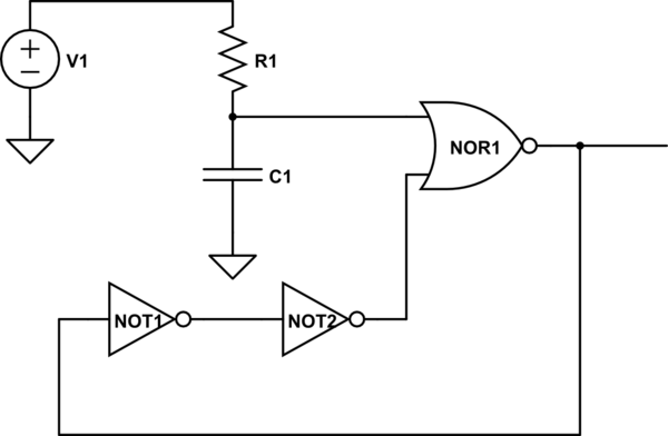
If you are open to use different types of gates, here is what you can do

simulate this circuit – Schematic created using CircuitLab
The RC delay will keep NOR gate output at 1 from the beginning, then switch to NOT function as required for oscillation.
Having said that, there is still "twilight" zone on the power up where gate output might be undefined. Adding pull-up on the output might help with that, but it will affect the oscillation frequency somewhat.
How can I start this oscillating with an initial value then make sure this value doesn't affect the operation of the circuit?
Your question is unclear whether you mean this circuit being in a circuit simulator or a physical form using real components.
In the simulator indeed this circuit will not start oscillating as the circuit solver can find an operating point where all stages basically output the same voltage that is at their input. Usually this voltage is near half the supply voltage.
To make it start you have several option. All you need to do is to "kick" it into action. I usually use a current pulse (ipulse component) to make a for example 10 uA current pulse of a few micro seconds. As the current returns to zero after the pulse, it does not influence the circuit anymore. You can inject the current into any internal node of the ring oscillator.
You can also use a vpulse to make a voltage pulse, put that source in between two inverters. Sometimes a pulse on the supply will also work.
In the real world this circuit starts up (given that it has enough loopgain) due to noise and disturbances. It will never be on the "dead" point that the simulator finds as that state has a very high gain so all noise and disturbances are amplified kicking the oscillator into action.