1
\$\begingroup\$

Under the electrical characteristics, the optocoupler 4N26 typical "forward voltage" is given as 1.2V. But for sizing the input resistor Im have hesitations.

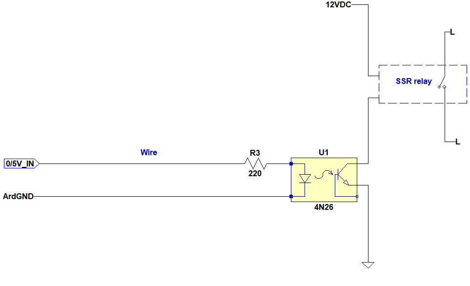
In my application as a control signal I will use an Arduino 5V digital output for the opto input. The optocpupler will then switch this SSR which requires 16mA to operate independent of input voltage. Here is the basic diagram:

enter image description here

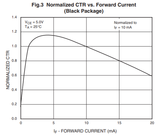
In a net tutorial I found this information: "The CTR depends on the LED input current (IF) and the CTR decreases from a maximum point when the input current is both increased and decreased. If you look at the below diagram, the top of the curve is around the 6mA point. This is where the chip is most efficient."

In my case I have the black package and below is for the CTR vs Forward current:

enter image description here

Here my questions:

1-) So in my case by looking at the plot above I choose the forward current IF as 4mA and from datasheet the forward voltage is typical 1.2V. So I calculate:

R = (5 - 1.2) / 0.004 = 950 Ohm.

So I conclude 1k.

But in many examples I see much smaller resistor value.

Am I doing something wrong here?

2-)

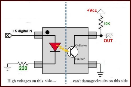
In some examples they place the resistor in return path. Does that have any significance? Her an example:

enter image description here

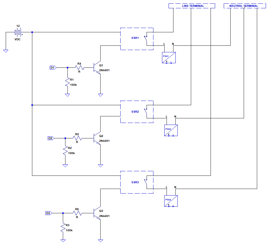
edit:

enter image description here

\$\endgroup\$

3 Answers 3

1
\$\begingroup\$

The 4N26 is a really cheap crummy optoisolator and has a guaranteed CTR of only 20% at 25°C. It will be worse at temperature extremes and with LED aging. So you would need a minimum of 80mA, but more like 120mA to be safe on CTR, but that's too much for the optocoupler LED. Note that the curve you show is normalized so CTR drops to more like 12% at 20mA.

4N36 has a more reasonable 100% CTR guaranteed so maybe you can choose 25mA drive but that's still a bit high for the Arduino and for good opto life. Or put a transistor on the SSR side to drive the SSR.

Note that the SSR already includes proper isolation so you may not require anything more than a BJT or MOSFET to drive the SSR if you don't need to keep the 12V power supply isolated. In such a case, I would use something like a 2N4401.

\$\endgroup\$
5
  • \$\begingroup\$ Thanks I think I will not go for opto. Please see my edit i.sstatic.net/Kbg61.png I used 2N4401 as you mentioned. Do you The 100k are for in case of floating input(necessary?), For this case and SSR would 220 Ohm for the base resistor enough? \$\endgroup\$
    – pnatk
    Commented Oct 9, 2018 at 12:32
  • 1
    \$\begingroup\$ @Spehro: Tip of the day: ° for ° and Ω for Ω. (It doesn't work in the comments.) \$\endgroup\$
    – Transistor
    Commented Oct 9, 2018 at 12:47
  • \$\begingroup\$ @Transistor Would 470Ω base resistor of 2N4401 (Vcc = 12V ) be sufficient for base resistor in this scenario? Im stuck between 220 and 860 \$\endgroup\$
    – pnatk
    Commented Oct 9, 2018 at 13:47
  • \$\begingroup\$ @Transistor. Good tip!. I'm on a laptop without the usual Alt-sequence here in darkest SEA. \$\endgroup\$ Commented Oct 9, 2018 at 14:07
  • \$\begingroup\$ If you assume a forced beta of 20, around 0.8mA base current is fine. R = 4.2/0.8 = 5.25K, so 4.99K or 4.7K will be fine. \$\endgroup\$ Commented Oct 9, 2018 at 14:08
0
\$\begingroup\$

It is because the maximum input current of the LED is 100mA (60mA for M version).

You rather drive the LED around 20-40mA to make sure the opto-transistor is conducting fully.

5-1.2/0.02 = 190 ohm so you can use 180 ohm.

\$\endgroup\$
2
  • \$\begingroup\$ 180 is a bit low how about 220? I dont wanna load the digital output current more than 20mA. \$\endgroup\$
    – pnatk
    Commented Oct 9, 2018 at 11:23
  • \$\begingroup\$ yes 220 would also work, you have quite a big range to play with. \$\endgroup\$
    – Damien
    Commented Oct 9, 2018 at 11:26
0
\$\begingroup\$

The phototranstor browns out over time, so the CTR ratio falls. You need to supply a consitent current. There are other optos with smaller current also. But your SSR device already has opto isolation, so an open collector BJT can solve this without problem. Open collector output can be used for relativelly long distances, if this is an issue.

EDIT:

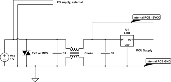
You can eliminate the worry about false triggering. The noise could come from Vcc and not from signal. The easiest is to use a BJT. If noise is a concern, then you might install a differential choke and cap, MOV where you suppy the output Vcc. Or viceversa, you add this filter to the input of MCU power supply and left unfiltered for external I/O signals.

schematic

simulate this circuit – Schematic created using CircuitLab

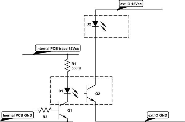
But most likely you won't have any issues even if the 12V Vcc goes 5m away, since you have also a low pass filter before and after LDO which supplies the MCU.

schematic

simulate this circuit

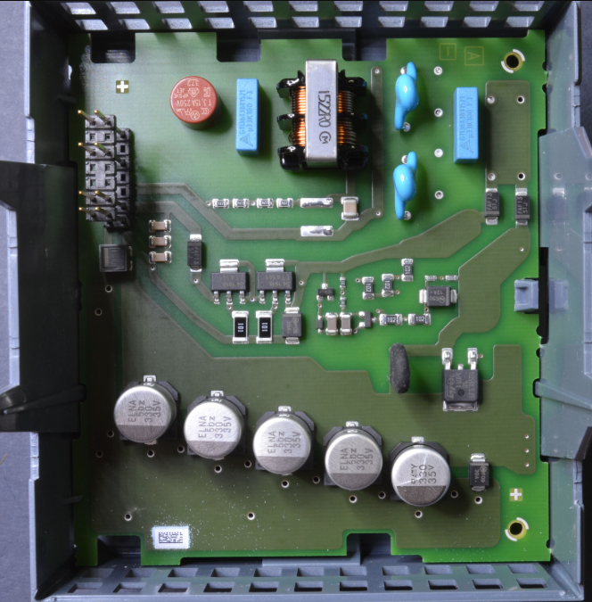
Professional PLC sytem using same power supply for MCU and IO with choke and opto coupled IO signals.

enter image description here

\$\endgroup\$
3
  • \$\begingroup\$ The wire length between arduino digital outputs and the SSR inputs will be 3 to 5 meters so Im stuck with with should I go for FET BJT or opto? Im worried about noise coupling and false triggering. \$\endgroup\$
    – pnatk
    Commented Oct 9, 2018 at 11:21
  • \$\begingroup\$ please see my edit I think I will go for BJT solution. But I dint undetand where do you place the filter and the choke. Please see my diagram maybe u migh make an edit on it otherwise becoming confusing. \$\endgroup\$
    – pnatk
    Commented Oct 9, 2018 at 12:40
  • \$\begingroup\$ @panicattack It's OK. You will not need a choke, anyway it goes from the PSU or 12V battery between the LDO or buck converter of Arduino or whatever you will power the Arduino with. MY example is an overkill for your needs, it's the way the industrial PLCs are built. \$\endgroup\$ Commented Oct 9, 2018 at 16:00

Your Answer

By clicking “Post Your Answer”, you agree to our terms of service and acknowledge you have read our privacy policy.

Not the answer you're looking for? Browse other questions tagged or ask your own question.