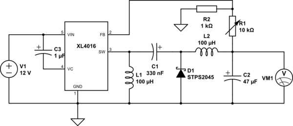
So I've tried to build a Zeta topology DC-DC converter based on a simple buck converter IC XL4016, which works perfectly in a regular buck topology. However, when hooked up in a Zeta topology as shown on the schematic below, the schematic becomes unstable.
If the output voltage is set using R1 potentiometer to, say, 9V, then everything is more or less fine at input voltages V1 < ~7V and V1 > ~12V except for +-0.5V changes in voltage with the input voltage. When the input voltage is close to the output voltage (V1 > 7V && V1 < 12V), the converter suddenly jumps to ~14-16V output voltage and "latches" in this state - no matter what the input voltage is (even if it becomes beyond the 7-12V range) or the potentiometer position, it stays at that output voltage until the power is cut off or the potentiometer is set all the way to minimum.
So, what could be the problem here both with the output voltage sudden rise and latching and with the output voltage a bit unstable (+-0.5V) outside the "death range"?
XL4016 datasheet: https://www.makerfabs.com/desfile/files/XL4016-Datasheet.pdf
P. S. It doesn't seem to be a problem with the maximum/minimum duty cycle: the duty cycle in zeta topology at input voltages close to the output ones becomes close to 50%, not 100% or 0%, and the XL4016 IC claims to be able to hadle the full 0%-100% duty cycle range.
I am using the Mastech HY3005 PSU for the input voltage, by the way.
The schematic works fine in Proteus simulation with the XL4016 IC changed to Lm2576-ADJ (I haven't found anywhere the XL4016 IC model)

simulate this circuit – Schematic created using CircuitLab
