0
\$\begingroup\$

I've recently been working on a breadboard compatible compact debouncing PCB. I found the MAX6816, a debouncing IC - check the spreadsheet here.

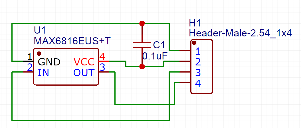
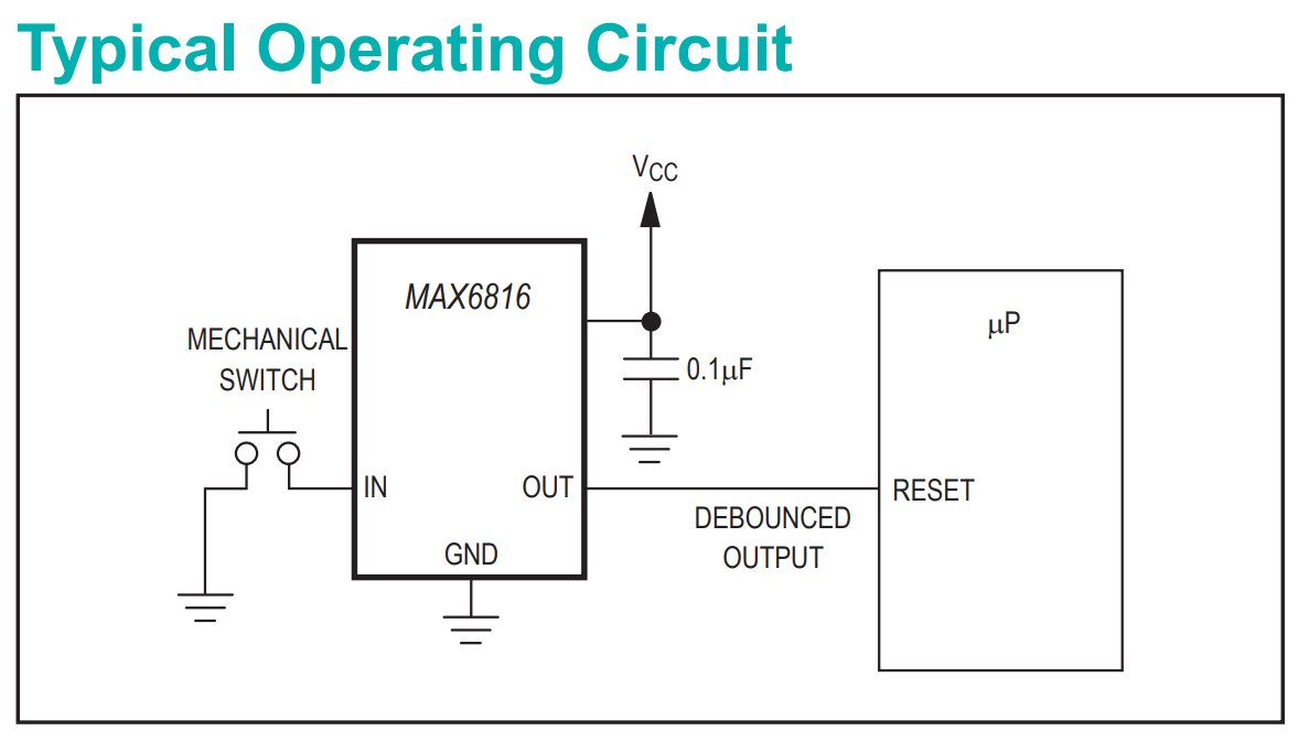
I made the below simple circuit as per the "Typical Operating Circuit" on the data sheet.

Following the "Typical Operating Circuit"

The datasheet does not show a resistor between ground and the button here:

"Typical Operating Circuit"

Should I add one to my circuit or would the IC include one?

Thanks for your help in advance.

\$\endgroup\$
2
  • \$\begingroup\$ Do you need a hardware solution or could you do your debouncing in software? \$\endgroup\$
    – Colin
    Commented Oct 19, 2018 at 10:02
  • \$\begingroup\$ @Colin yeah a hardware one specific for project using this as a manual clock step. \$\endgroup\$
    – Oleenick
    Commented Oct 19, 2018 at 12:06

1 Answer 1

1
\$\begingroup\$

The IC has an internal pullup resistor. Like most resistors in ICs it is loosely specified (a 3:1 range) and (because the manufacturer wants to maximize the market) rather on the high side.

enter image description here

So the minimum switch current with a 5V supply is 50uA. Some switches would be more reliable with a higher current (often specified on the switch datasheet as minimum current) and if that is so you can add an external pullup resistor, so the effective pullup will be the parallel combination of the internal and external resistors.

\$\endgroup\$

Your Answer

By clicking “Post Your Answer”, you agree to our terms of service and acknowledge you have read our privacy policy.

Not the answer you're looking for? Browse other questions tagged or ask your own question.