1
\$\begingroup\$

There's a DC Black Box, and my goal is find the Thevenin resistance within the black box. By connecting a digital mulitmeter to the terminal, I have found that the "open-circuit" output is \$0.647\ \text{V}\$. Then I connected a variable resistance box and the multimeter in parallel to the black box. Then I increased the load resistance to \$1410\ \Omega\$ till I got 50% of the open circuit reading. Which is \$0.3235\ \text{V}\$.

Then I know that \$V=I\cdot R_{th}\$

I proceeded to find \$I\$ by using the relationship created by the load, \$0.3235 = I\cdot 1410 \rightarrow I = 0.000230780142\ \text{A}\$

Then using this value I solved for \$R_{th}\$

\$0.647 = 0.000230780142\cdot R_{th} \rightarrow R_{th} = 2803 \Omega.\$

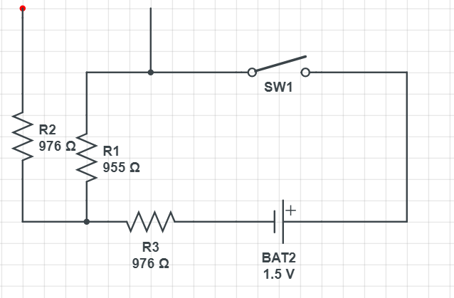
Then I was allowed to check the Black Box contents and the circuit looked like this:

enter image description here

Shouldn't the effective resistance then be, \$R = R_3 + (\frac{1}{R_1} + \frac{1}{R_2})\$?

This doesn't even come close my calculation.

Any help would be greatly appreciated.

\$\endgroup\$

2 Answers 2

1
\$\begingroup\$

To find the Thevenin resistance you divide the open-circuit voltage by the short-circuit current. The current value you used is not the short circuit current. However, it turns out that the resistance value you used (1410 \$\Omega\$) is itself \$R_{TH}\$. See if you can figure out why.

\$\endgroup\$
5
  • \$\begingroup\$ I have to say, I'd never actually thought of using a variable resistor to determine \$R_{th}\$ the way the OP has before =) \$\endgroup\$
    – Shamtam
    Commented Oct 22, 2018 at 1:03
  • \$\begingroup\$ I actually saw this in my notes however I have no idea how to calculate short-circuit current of this system. \$\endgroup\$
    – fynmnx
    Commented Oct 22, 2018 at 1:23
  • 1
    \$\begingroup\$ The relationship between output voltage and current is linear. You have two points on that line, one with an open circuit and the other with 1410 \$\Omega\$ as a load. Plot these two points and extrapolate the line to find the value of output current when the output voltage is zero. \$\endgroup\$ Commented Oct 22, 2018 at 1:26
  • \$\begingroup\$ Do you have any idea about what is wrong with my circuit analysis calculation of \$R_{th}\$? \$\endgroup\$
    – fynmnx
    Commented Oct 22, 2018 at 2:10
  • \$\begingroup\$ You can't add a resistance (\$R_3\$) to a conductance (\$\frac{1}{R}\$). @Shamtam tried to tell you that. \$\endgroup\$ Commented Oct 22, 2018 at 11:18
0
\$\begingroup\$

Where do you get \$R_{th} = R_3 + (\frac{1}{R_1} + \frac{1}{R_2})\$?

Hint: Try re-drawing the circuit in the black-box to arrange your open-circuit terminals to be oriented vertically.

\$\endgroup\$
2
  • \$\begingroup\$ I drew this vertically, I think I see it now. Is it \$\frac{1}{R_1} + R_2 + R_3\$? \$\endgroup\$
    – fynmnx
    Commented Oct 22, 2018 at 1:17
  • \$\begingroup\$ No. I assume you're looking for the resistance between the two points at the upper-most part of the picture, and that the switch is closed. From there, what do you do with the DC source (BAT2), and then how do you get the equivalent resistance between the two points at the top of the picture? \$\endgroup\$
    – Shamtam
    Commented Oct 22, 2018 at 2:49

Your Answer

By clicking “Post Your Answer”, you agree to our terms of service and acknowledge you have read our privacy policy.

Not the answer you're looking for? Browse other questions tagged or ask your own question.