0
\$\begingroup\$

I can't work out what the issue with my setup to control a 2.5" hard drive BLDC motor is. I have a 3 pole 2.5" hard drive connected to the following drive circuit, but the motor isn't spinning.

schematic

simulate this circuit – Schematic created using CircuitLab

I'm using a current sinking shift register to drive the MOSFETs so they need to be pulled up by default. The motor driver seems to be working correctly, the arduino code is simply

static uint8_t motorVectors[6] = { 0b100100, 0b100001, 0b001001, 0b011000, 
0b010010, 0b000110};
int vectorPos;
void setup() {
  Serial.begin(9600);
  for(int x=2; x<8;x++){
    pinMode(x,OUTPUT);
  }
}

void loop() {
//AB
  digitalWrite(2, 0);
  digitalWrite(3, 0);
  digitalWrite(4, 1);
  digitalWrite(5, 1);
  digitalWrite(6, 1);
  digitalWrite(7, 0);
  Serial.println("AB");
  delay(10);

//AC
  digitalWrite(2, 0);
  digitalWrite(3, 0);
  digitalWrite(4, 1);
  digitalWrite(5, 0);
  digitalWrite(6, 1);
  digitalWrite(7, 1);
  Serial.println("AC");
  delay(10);

//BC
  digitalWrite(2, 1);
  digitalWrite(3, 0);
  digitalWrite(4, 0);
  digitalWrite(5, 0);
  digitalWrite(6, 1);
  digitalWrite(7, 1);
  Serial.println("BC");
  delay(10);

//BA
  digitalWrite(2, 1);
  digitalWrite(3, 1);
  digitalWrite(4, 0);
  digitalWrite(5, 0);
  digitalWrite(6, 1);
  digitalWrite(7, 0);
  Serial.println("BA");
  delay(10);

//CA
  digitalWrite(2, 1);
  digitalWrite(3, 1);
  digitalWrite(4, 1);
  digitalWrite(5, 0);
  digitalWrite(6, 0);
  digitalWrite(7, 0);
  Serial.println("CA");
  delay(10);

//CB
  digitalWrite(2, 1);
  digitalWrite(3, 0);
  digitalWrite(4, 1);
  digitalWrite(5, 1);
  digitalWrite(6, 0);
  digitalWrite(7, 0);
  Serial.println("CB");
  delay(10);
}

all seems to be working, I don't have an oscilloscope so I cant check the output waveforms over time but the output of the driver seems to be working correctly when I test each phase shown in the code.

I there anything glaringly wrong?

I have checked other answers and they seem to agree with the setup I have here.

\$\endgroup\$
6
  • \$\begingroup\$ what makes you think something is wrong? you say everything "working correctly" \$\endgroup\$
    – user16222
    Commented Oct 23, 2018 at 10:42
  • \$\begingroup\$ the motor isnt spinning, sorry completely forgot to add that! \$\endgroup\$
    – B_Gsy
    Commented Oct 23, 2018 at 10:56
  • 2
    \$\begingroup\$ right... that quite a critical observation... So Question1 : are you intending to run this open-loop as there doesn't seem to be any zonal information. Question2: you appear to be turning three devices on at any one time, BLDC needs two legs engaged and this two devices. Question3: your pullup on the ntype will default those to be ON, is this what you want. \$\endgroup\$
    – user16222
    Commented Oct 23, 2018 at 11:18
  • \$\begingroup\$ 1) yes I just want it to be open loop, I don't need speed control. 2) combining questions 2 and 3, yes I need the pulled up as I'm using an current sinking shift register to drive the mosfets. as for turning 3 devices on at any one time, there should only ever be 2 transistors on per phase. for example AB: Leg-A PMOS: on NMOS: off, Leg-B PMOS: off NMOS: on, Leg-C PMOS: off NMOS: off \$\endgroup\$
    – B_Gsy
    Commented Oct 23, 2018 at 11:23
  • \$\begingroup\$ Can you indicate which Arduino pins are connected to which FETs? \$\endgroup\$
    – Phil G
    Commented Oct 23, 2018 at 14:22

2 Answers 2

1
\$\begingroup\$

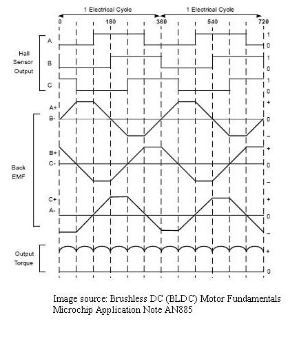
The first thing I would to would be test commutation, you should be able to turn one pole on at a time and have the motor turn to that position (or just measure the voltage at the motor). An oscilloscope would be really handy to make sure your waveform is working right.

You should see something like this:

enter image description here Source: https://www.instructables.com/id/BLDC-Motor-Control-with-Arduino-salvaged-HD-motor/

Make sure there is no load on the motor (these motor's do not have very high torque loads)

You may need to ramp the motor's speed to get it to turn from a dead start.

Another thing you could try is run your code and then twist the motor by hand to see if you could get it to start.

\$\endgroup\$
1
\$\begingroup\$

With BLDC motors and open loop commutation, you can't immediately commutate at the RPM you desire. If your stator field's RPM is far greater than your rotor's RPM, then the rotor will never "catch up" to the stator rpm. We would call this "slip" in the AC motor world.

But this is the BLDC world, and things are different. We must commutate synchronously, or the system will not work.

The solution here is to ramp or soft-start the motor. Don't immediately commutate your stator at 5000 rpm (for example). You must first ramp the rpm from 0 up to 5000 rpm in some interval that works well for your system. This gives the rotor a chance to "catch up" to the stator field before switching it again.

An obvious symptom of an out of phase commutation is a buzzing sound. I wonder if you hear any noise when you try to run your motor or not?

\$\endgroup\$

Your Answer

By clicking “Post Your Answer”, you agree to our terms of service and acknowledge you have read our privacy policy.

Not the answer you're looking for? Browse other questions tagged or ask your own question.