2
\$\begingroup\$

I'm experimenting with the 74LS181 ALU (see here if you like), and it is going well, but I am unable to figure out how to use the A=B, A>B, and A<B comparator functions.

The datasheet states, "The comparator output (A=B) of the device goes HIGH when all four function outputs (not F0 to not F3) are HIGH and can be used to indicate logic equivalence over 4 bits when the unit is in the subtract mode."

This is rather confusing. If I'm comparing A and B, I would think the A=B output would go HIGH any time A was equal to B. (That is the point after all.) Also, I'm not sure what it means by "...when the unit is in the subtract mode." There is no such mode on this chip.

Further into the same paragraph, it says, "The A=B signal can also be used with the Cn+4 signal to indicate A>B and A<B." That sounds nice, but it doesn't explain HOW to do this. Do I have to send the A=B output signal into another logic gate along with the Cn+4 output signal in order to get a result?

What I am hoping to achieve is to have a simple set of output LED's which I will label A=B, A>B, and A<B such that when I have a 0 on the A inputs and a 0 on the B inputs, then the A=B LED will be lit. And when I have a 1 on the A inputs and a 0 on the B inputs, then the A>B LED will be lit. Likewise for A<B.

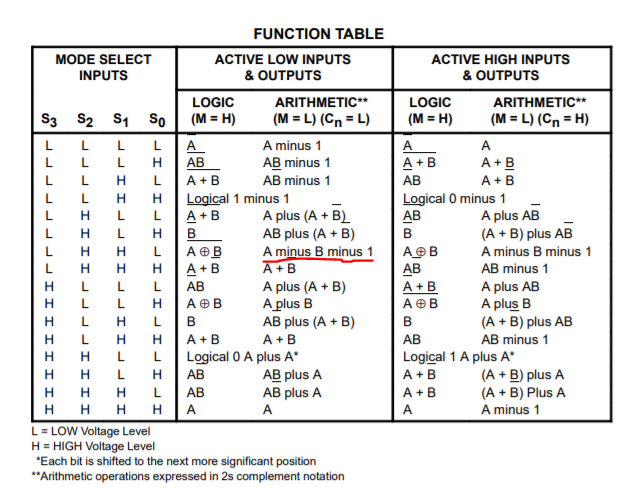
This chip is pretty nice ... though a bit quirky at times in my opinion For example, why is it A minus B minus 1 as opposed to just A minus B? What good is A minus B minus 1? But otherwise it provides quite a few useful logic functions into a single chip, so I'd like to figure out this comparator thing.

\$\endgroup\$
2
  • \$\begingroup\$ Welcome to EE.SE. The LS181 is a ALU, not a comparator. That it outputs an A=B flag is just part of the design. If you want just a 4 bit comparator try a 74LS85. It has the outputs you want. \$\endgroup\$
    – user105652
    Commented Oct 27, 2018 at 5:03
  • 1
    \$\begingroup\$ Thanks for the reply. I'm aware of the 74LS85, but I don't want just a comparator. I'm aware that the 74LS181 is an ALU, but the datasheet lists these capabilities as its available features: add, subtract, COMPARE, double, and others. Also, the datasheet says it can indicate A>B and A<B. \$\endgroup\$
    – blixel
    Commented Oct 27, 2018 at 5:08

2 Answers 2

4
\$\begingroup\$

I'm not sure what it means by "...when the unit is in the subtract mode." There is no such mode on this chip.

There certainly is: enter image description here

When the "Mode Select" inputs are set to LHHL (or 0110), the ALU calculates A-B-1. This is called the "subtract mode".

"The comparator output (A=B) of the device goes HIGH when all four function outputs (not F0 to not F3) are HIGH and can be used to indicate logic equivalence over 4 bits when the unit is in the subtract mode."

This is rather confusing. If I'm comparing A and B, I would think the A=B output would go HIGH any time A was equal to B.

So if you calculate A - B - 1, what result do you get when A = B?

You get -1, which is represented by all \$\rm \overline{F}\$ bits being high.

So the chip is providing exactly the behavior you say you expect.

Further into the same paragraph, it says, "The A=B signal can also be used with the Cn+4 signal to indicate A>B and A

It's explained in the very next paragraph:

The Function Table lists the arithmetic operations that are
performed without a carry in. An incoming carry adds a one to
each operation. Thus, select code LHHL generates A minus B
minus 1 (2s complement notation) without a carry in and
generates A minus B when a carry is applied. Because
subtraction is actually performed by complementary addition
(1s complement), a carry out means borrow; thus a carry is
generated when there is no underflow and no carry is
generated when there is underflow.

If A < B, then A - B - 1 will produce underflow, which will result in the carry bit not being asserted. If A > B then there will be no underflow and the carry bit will be asserted.

For example, why is it A minus B minus 1 as opposed to just A minus B? What good is A minus B minus 1?

Because this is easier to compute with the absolute minimal number of transistors.

In two's complement, A - B is the same as \$\rm A + \overline{B} + 1\$. So A-B-1 is just inverting B and adding to A.

And, as the quotation above says, you can get just A-B by asserting the Carry-in bit while doing the A-B-1 operation.

\$\endgroup\$
6
  • \$\begingroup\$ Re why A-B-1 ... Another reason is that if you cascade the chips to work on more than 4 bits, you need to know whether you're working on the least significant bits (in which case you need to add 1 when negating B) or not (in which case you don't) to implement A-B. \$\endgroup\$
    – Jules
    Commented Oct 27, 2018 at 8:50
  • \$\begingroup\$ ... When the "Mode Select" inputs are set to LHHL (or 0110), the ALU calculates A-B-1. This is called the "subtract mode".... OK, I can't find this in the datasheet, so I'm not sure how you knew that, but thanks. Is it only true for that one subtraction, or is it true for A minus 1, AB minus 1, and so on? Where did you find this? \$\endgroup\$
    – blixel
    Commented Oct 27, 2018 at 14:27
  • \$\begingroup\$ @blixel I quoted the relevant paragraph from the data sheet in my answer. \$\endgroup\$
    – The Photon
    Commented Oct 27, 2018 at 15:17
  • \$\begingroup\$ I just like things to be clear and unambiguous. And there's nothing in the datasheet that says "Subtract mode is the same as A minus B minus 1." Anyway, thanks for the responses and I'll get back to the actual hardware to try this out as soon as I can. \$\endgroup\$
    – blixel
    Commented Oct 27, 2018 at 16:46
  • \$\begingroup\$ @blixel, for what it's worth I agree this is not the most transparent data sheet in the world. Back when this was written, I think they expected you to just work it out from the logic diagram if you had any questions. \$\endgroup\$
    – The Photon
    Commented Oct 27, 2018 at 16:53
1
\$\begingroup\$

Although the question is already a bit older I just had the same one, read the answers here and then figured it out on my on:

You quoted the following sentences from the datasheet:

The comparator output (A=B) of the device goes HIGH when all four function outputs (not F0 to not F3) are HIGH and can be used to indicate logic equivalence over 4 bits when the unit is in the subtract mode.

But the key to your (our) question lies in the next one:

The A = B output is open collector and can be wired-AND with other A = B outputs to give a comparison for more then four bits.

Here you can find the explanation what an open collector is: https://en.wikipedia.org/wiki/Open_collector

The means that when all outputs F1-4 are high the base of this output transistor is high and the A=B pin goes into a HIGH-Z state, i.e. it behaves like an open switch. Whenever not all F pins are high the base of the transistor is low and therefore the transistor conducts and is pulling the A=B pin to ground.

You can easily demonstrate this behaviour by connecting an LEDs anode via a resistor to 5V and the cathode to the A=B bin. The LED will be on except when all F pins are high, then it will go off. I was just able to demonstrate this myself.

This "works" by the way in all modes, although it does not really makes sense there. For example all control lines low (for active high inputs) or all control lines high (for active low inputs) causes the result of the ALU to be the A input. When you set all A pins high the output will also be high. Then the A=B pin will also go HIGH-Z. Therefore it makes only really sense to look at this pin when subtracting A from B.

\$\endgroup\$

Your Answer

By clicking “Post Your Answer”, you agree to our terms of service and acknowledge you have read our privacy policy.

Not the answer you're looking for? Browse other questions tagged or ask your own question.