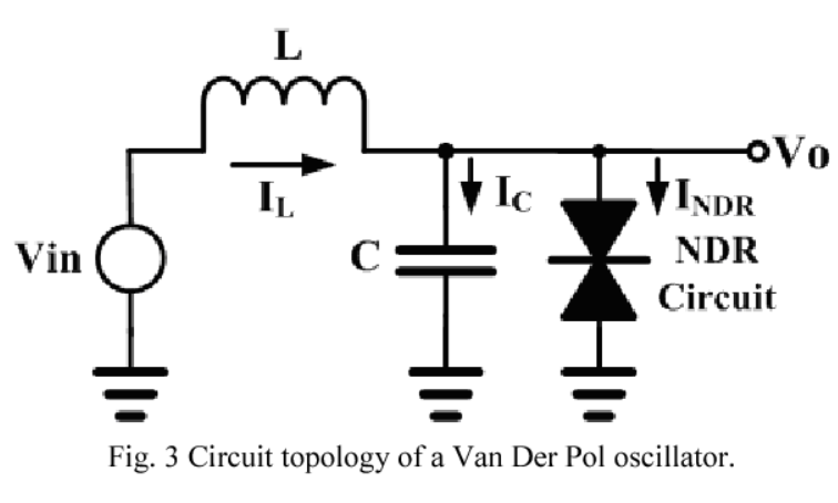
Can someone explain what is going on?
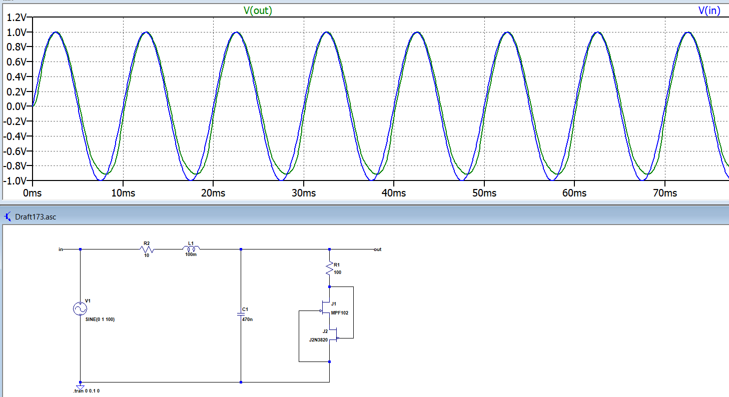
In your top schematic, you're exciting the circuit with a sinusoid, and it's just following along, presumably because you're not giving the oscillator section enough supply voltage to do anything.
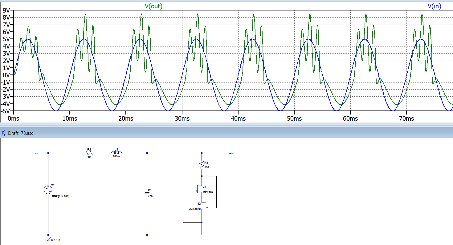
In the bottom circuit, you see oscillation happening at the peaks of the input sine wave, but not at the valleys. Presumably this means that if you just gave it a straight +5V it would oscillate. If the JFETs were perfectly matched I would expect it to oscillate at the valleys of the sine wave, too.
Is that what this oscillator supposed to output?
I doubt it. Usually you want to feed an oscillator a DC voltage and have it give you a periodic output. You're giving it a sinusoid where it's DC power would usually be applied.
I'm especially trying to see non linear
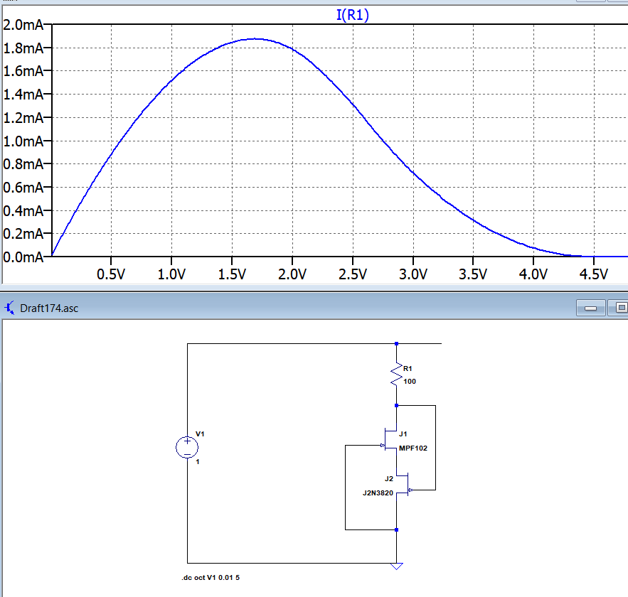
Well, you're seeing it! When your supply voltage is below about 3V or so, the oscillator's not starting up. Then it gets up above 3V and it oscillates until it drops back down again. Replace your sinusoid with a DC voltage, diddle with the value until you see oscillation, and you will, by definition, be seeing nonlinear behavior.
and chaotic behavior.
Oi. First, if the intent of whatever article you're going off of was to feed the oscillator with DC, you're most likely not going to get chaotic behavior from that circuit. There's a principle in nonlinear system that in order to see chaotic behavior you either need three energy storage devices (i.e., inductors and capacitors), or you need two energy storage devices and a forced time-varying input.
Your circuit as shown does satisfy the latter condition, so you may be able to find one or more families of operating points that gives you chaotic behavior. I would expect that for input frequencies close to the higher sub-harmonics of the natural oscillation frequency the oscillator will "lock in" to a harmonic of the input frequency and the output will be boring. For very low input frequencies the behavior will be technically chaotic, but not strikingly so. Somewhere in between (at appropriate input amplitudes and bias) you will find joy.
To look for chaotic behavior, set up a graph of inductor current against capacitor voltage. Technically this is the state-space trajectory of the system. Now look for a trace that seems to be orbiting a strange attractor. Now vary the input frequency, amplitude, and bias, and see how the character of the trace varies. If you're doing it experimentally you'd need to vary the input amplitude, frequency, and maybe the bias, and see if you find joy.
If you want a simple, realizable electronic circuit that exhibits autonomous chaotic behavior (i.e., that doesn't need to be driven by a sine wave) do a web search on Chua's Circuit. I believe there are single-transistor implementations* of it, but it's easier to do an op-amp implementation. There should be projects on the web -- if not, check back here.
* I remember building one by accident in my undergrad years and recognizing it's behavior as chaotic, but it was when chaos in circuits was only just being recognized as a thing, and my school did not feature profs who stayed au courant, so it remained my personal curiosity.

