4
\$\begingroup\$

I am trying to understand how an arbitrary noise spectrum is sampled by an ADC. Let the broadband noise floor be, for example, \$e_n\$ = 5nV/√Hz @ 1kHz and the 1/f noise be \$E_{1/f}\$ = 2 μV peak-peak integrated over 0.1 to 10 Hz (specified in the manner of most amplifier datasheets). If I make a single measurement of this noise (say with a ΣΔ ADC) the noise with an integration time T, what is the amplitude of uncertainty in my sample (neglecting quantization noise)?

Another way of posing this question; most ΣΔ ADCs appear to specify a peak-to-peak input-referred noise for a single measurement under various conditions (e.g filter mode, data rate, PGA gain, Vref, etc.). Given a known input noise spectrum as described above, how do I compute a noise amplitude to compare with the ADC input referred noise to know whether I can resolve my input noise in a given configuration?

If, for example, the sample interval is T=10μsec, would the sampled RMS amplitude just be \$e_n \sqrt{1/T}\$ = 1.6μV (assuming the 1/f noise is negligible at this BW)? Then if I average many just measurements the measurement improves by \$\sqrt{N}\$ which is equivalent to using a longer integration time \$NT\$?

EDIT: Also, what if I am making a precision DC measurment with a long integration time such that 1/f noise dominates? My 1/f noise spec only goes down to 0.1Hz so how do I estimate noise for integration times longer than 10 seconds? Do I need to extrapolate the 0.1 to 10 Hz noise amplitude to lower frequencies?

[Note that this question pertains to the mathematics of sampled noise not about the challenges in measuring this low noise level, the subtleties of particular ADC technologies, or low noise circuit layout.]

\$\endgroup\$
3
  • \$\begingroup\$ If I remember back to university this is determined by Gaussian distribution. \$\endgroup\$ Commented Nov 8, 2018 at 19:46
  • \$\begingroup\$ This answer is helpful in connecting the noise density to its distribution electronics.stackexchange.com/a/130463/5563 but only partly answers my question. \$\endgroup\$
    – Mike
    Commented Nov 8, 2018 at 19:59
  • 1
    \$\begingroup\$ It seems to me that the ADC is a red herring in this question. Don't confuse the sample interval with the sample-and-hold, ramp-and-hold performance, or the "aperture" time of the ADC input stage. In most situations the sampling is assumed to be instantaneous not an integral of the interval. This is further complicated in a ∑∆, as the actual sample aperture is orders of magnitude faster than the sample interval and the spectrum is shaped by the filtering. \$\endgroup\$ Commented Nov 8, 2018 at 20:02

2 Answers 2

1
\$\begingroup\$

Another way of posing this question; most ΣΔ ADCs appear to specify a peak-to-peak input-referred noise for a single measurement under various conditions (e.g filter mode, data rate, PGA gain, Vref, etc.). Given a known input noise spectrum as described above, how do I compute a noise amplitude to compare with the ADC input referred noise to know whether I can resolve my input noise in a given configuration?

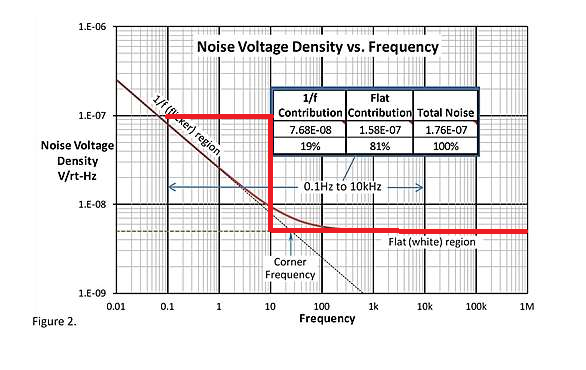
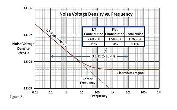
The easiest way to do this is to call the 1/f noise flat

enter image description here Source: https://www.edn.com/electronics-blogs/the-signal/4408242/1-f-Noise-the-flickering-candle-

Since we already know how to handle white noise sources, it's easier to work with them. For example with this amplifier I would draw a line at 10e-6 from 0.1 to 10Hz

enter image description here

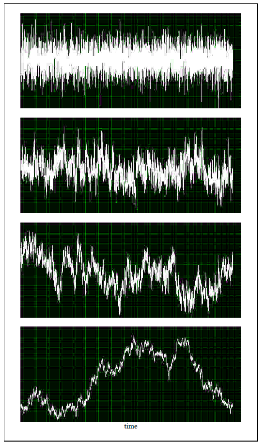
There isn't a way (currently) to mathematically sample a 1/f noise distribution mathematically. Why? because 1/f noise is more like a random walk, and the noise values now depend on the previous noise values. A close approximation is to generate a white noise distribution and then filter it with a low pass filter.

There are ways to simulate 1/f noise, and you could match up the amplitude, as described in this paper: 1/f noise: a pedagogical review.

enter image description here

Figure 25: 1/f noise generated with the algorithm described in section 10, amplitude vs. time(both linear scales and arbitrary units); starting from top, = 0, 1, 1.5 and 2.

Sourced: Figure 25 1/f noise: a pedagogical review.

\$\endgroup\$
1
  • \$\begingroup\$ The first equation in the Bruce Trump article you linked to seems like the correct integral of 1/f noise, however, I had been using the equation on page 19 of ti.com/lit/ug/slau522/slau522.pdf (also from TI) which takes the ln(sqrt) rather than the sqrt(ln). The result is actually pretty close for 0.1 to 10Hz but it still seems that Bruce is right and Arthur Kay made an error. \$\endgroup\$
    – Mike
    Commented Nov 9, 2018 at 6:58
0
\$\begingroup\$

You've asked three or four questions, I'm going to answer the one in the title, and leave the rest as an exercise.

how (is) an arbitrary noise spectrum sampled by an ADC?

Start by assuming a perfect sampler. The sampler aliases the noise presented to it. Assuming that you're regularly sampling at a rate of \$f_s\$, and that the noise is uncorrelated, you get something like $$ S_s\left(f\right) = \sum_{n=-\infty}^{+\infty}{S(f+nf_s)} $$ where \$S_s(f)\$ is the spectral density after sampling. Note that sampling perfectly white noise isn't going to end well -- \$S_s(f)\$ will be infinite everywhere.

  • Aperture time of the ADC was mentioned -- this affects the spectrum of the noise that's input to the sampler. In that case you're (roughly) running the incoming signal (and noise) through a filter that averages over the aperture time.
  • You mentioned \$\Sigma\Delta\$ conversion. That gets complicated (and I don't have the time, sorry) -- basically, the converter converts to digital at a high rate, then filters the heck out of the resulting signal, then samples that at a lower rate, then hands the result to you. To analyze the converter fully you need to model both steps (and any intermediate sampling steps, too, which some \$\Sigma\Delta\$ feature)
  • If the \$1/f\$ noise that you mention starts to kick in well below the sampling rate it will show up pretty much unmolested. So will the \$1/f^2\$, \$1/f^3\$, and all the other \$1/f^n\$ noise that they didn't bother to mention (or that is called out as "drift"), plus the similar noise that your circuit delivers to the ADC.
  • Note that for SAR and other high-bandwidth ADCs, the front-end circuitry often contributes noise well in excess of typical thermal noise. Semiconductor manufacturers let you have this noise at no extra charge. Be thankful if you need it. If you don't, read the data sheet carefully.
\$\endgroup\$

Your Answer

By clicking “Post Your Answer”, you agree to our terms of service and acknowledge you have read our privacy policy.

Not the answer you're looking for? Browse other questions tagged or ask your own question.