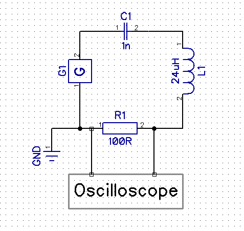
I'm trying to experimentally verify my calculations on resonance on a simple series LC circuit.
To prove resonance, I'm measuring the amplitude on the series resistor. When the amplitude is the highest, then resonance has occured.
I'm using WE coil:
And a ceramic capacitor in series. Measured both elements values by a LCR meter.
By the formula:
We can calculate that the resonance frequency should be around 1.03 MHz.
But in reality, the measurements doesnt add up.
Firstly, on the calculated resonance frequency, there is very little voltage drop on the resistor. Secondly there are multiple maximums via the 1-100 MHz frequency range:
At 4.6 MHz = 100 mV
At 26 MHz = 80 mV
At 70 MHz = 100 mV
I'm guessing that at the 26 and 70 MHz peaks, the parasitics kicked in, but what got me more confused is that when I remove the capacitor, the voltage maximums remain at the same frequencies. Worth noting that the 4.6 MHz peak corresponds to self resonant frequency of the coil by the datasheet. What is the reason for this behaviour?

