3
\$\begingroup\$

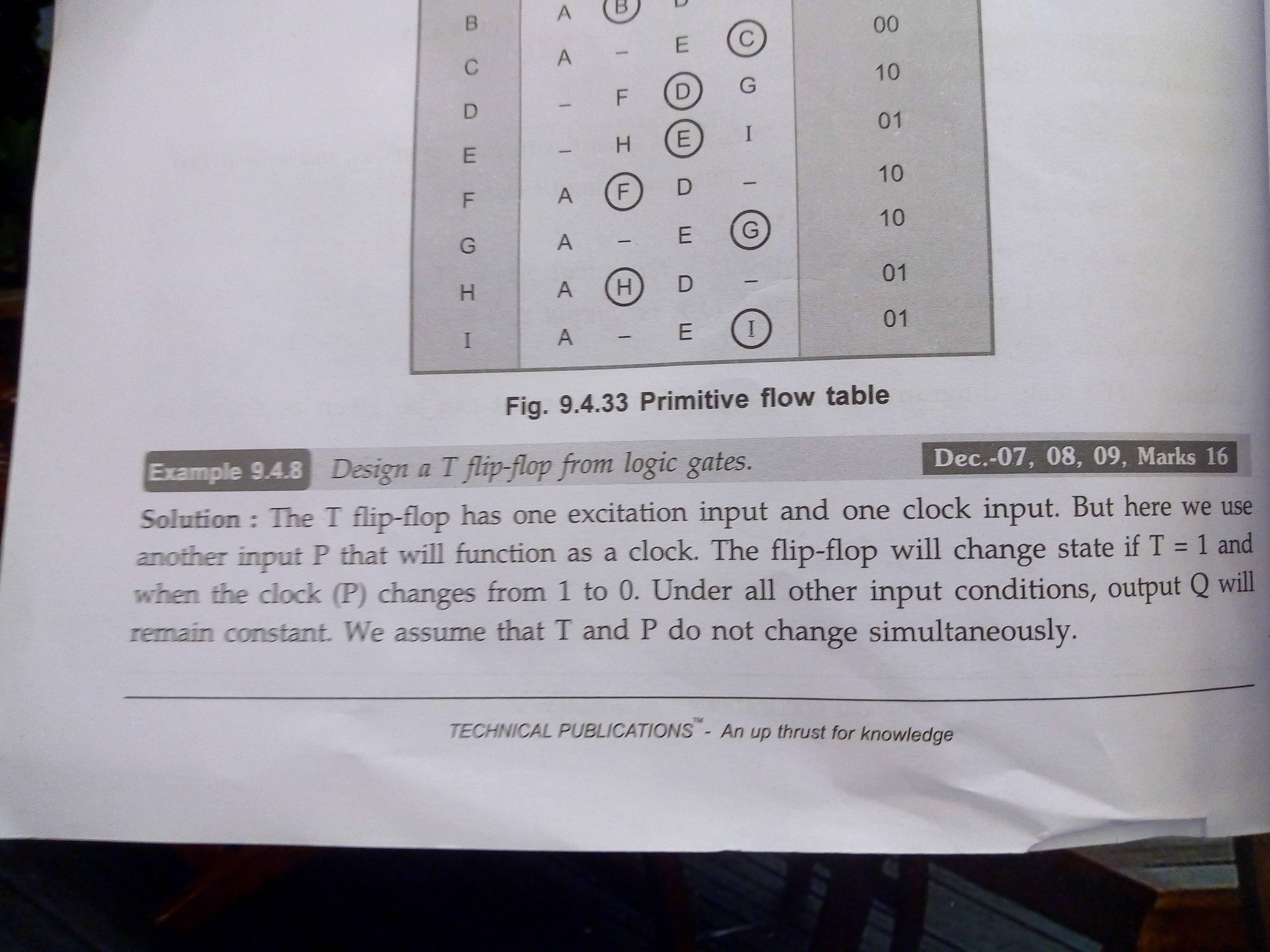
I am supposed to design a T flip flop using logic gates (asynchronous sequential circuit) and also draw the state diagram. I don't really understand why the output doesn't change from 0 to 1 when there is a transition from B to D in the given figure below, because for the T flip flop the state 11 causes toggle action, doesn't it? Can someone help me figure this out.

enter image description here

enter image description here

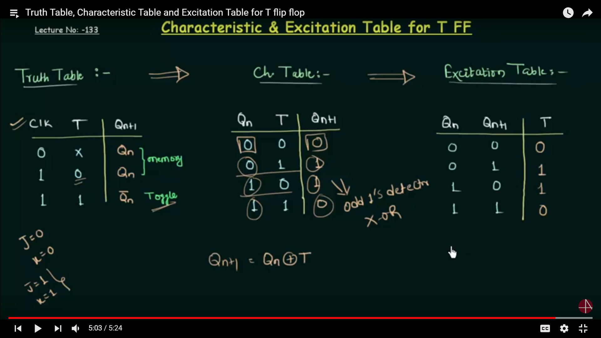
Truth table for T flip flop:

enter image description here

\$\endgroup\$
1
  • 3
    \$\begingroup\$ Welcome to EE.SE! This appears to be a homework question. As such, you need to show us your work so far, and explain which part of the question you're having trouble with. For future reference: Homework questions on EE.SE enjoy/suffer a special treatment. We don't provide complete answers, we only provide hints or Socratic questions, and only when you have demonstrated sufficient effort of your own. Otherwise, we would be doing you a disservice, and getting swamped by homework questions at the same time. See also here. \$\endgroup\$
    – Dave Tweed
    Commented Nov 25, 2018 at 12:58

1 Answer 1

1
\$\begingroup\$

No, it's the 1→0 transition of P (TP = 10) that causes the output to toggle.

\$\endgroup\$

Your Answer

By clicking “Post Your Answer”, you agree to our terms of service and acknowledge you have read our privacy policy.

Not the answer you're looking for? Browse other questions tagged or ask your own question.