0
\$\begingroup\$

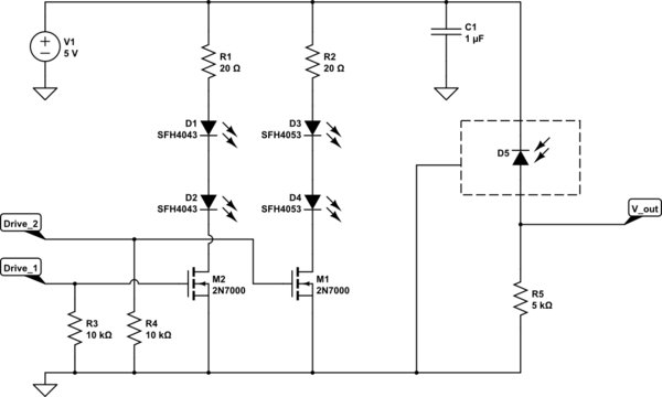
I'm trying to make a circuit for a pulse watch, which should be capable of measuring blood SpO2. I use 2 LEDs for each wavelength (respectively 660nm and 940nm) to shine at the upper wrist. The reflected light is supposed to be picked up by the following photodiode: https://dk.farnell.com/hamamatsu/s1223/photodiode-pin-to-5/dp/1495587

Everything should be wired to my Arduino and the supplied voltage is 5V.

Below you can see the circuit:

Circuit

Do you think I will need any operational amplifier for this photodiode? - In the case of yes, since I'm new to this, which one would you recommend?

\$\endgroup\$
9
  • \$\begingroup\$ That’s a design question. Please show us your insights to define the signal conditioning for the Arduino interface. What’s your question against the design? \$\endgroup\$
    – PDuarte
    Commented Nov 28, 2018 at 12:42
  • \$\begingroup\$ Oh i see! Well its just an Arduino UNO. Each of the LEDs are placed roughly 0.5cm away from the sensor - was that what you were looking for? \$\endgroup\$ Commented Nov 28, 2018 at 12:51
  • 1
    \$\begingroup\$ It all depends on how much reflected light is received and what filtering on the signal you are intending to apply and the resolution of your ADC. \$\endgroup\$
    – Andy aka
    Commented Nov 28, 2018 at 12:53
  • \$\begingroup\$ You have to realize that the photodiode will react to all light. If there's too much unwanted light falling onto the photodiode the light from the LEDs might become insignificant compared to that unwanted light. The signal on V_out might become very small, smaller than what the ADC in an Arduino can reliably measure. It is hard to say "do this and it will be fine" because it depends. You might want to look at similar designs and see what circuit is used there right after the photodiode. \$\endgroup\$ Commented Nov 28, 2018 at 12:57
  • 1
    \$\begingroup\$ "I have no clue how much light will be reflected" - Not to be rude, but if you don't know how much light the PD will get, how do you expect us to tell you whether you need an op amp to handle that unknown signal? Hint - the answer is probably yes, but that's just because it almost always is. And your blind faith that you will be able to deal with problems in software is quite likely to get you in deep trouble somewhere down the line. Just because you are comfortable with software does not mean that it's a universal panacea. Start learning about the hardware. \$\endgroup\$ Commented Nov 28, 2018 at 14:22

1 Answer 1

0
\$\begingroup\$

Generally speaking, you can consider the following:

A transimpedance amplifier (using an opamp) is used for

  • Higher speeds - If the photodiode has a significant capacitance.
  • Higher amplification - You may get into trouble with biasing otherwise.
  • Better linearity - The photodiode biasing voltage is more constant.
  • Low output impedance - The opamp also acts as a buffer.

Just the regular resistor biasing can be used for

  • Lowest power consumption - Only a single branch with current (usually negligible).
  • Lower noise - No added noise by the opamp + possible compensation capacitor.
  • Simplicity - No need to look at stability or choosing a suitable opamp.

My advice is to keep a transimpedance amplifier in mind. When used correctly it almost always leads to a better performance. If you're designing a PCB for example, you can always choose not to mount the opamp if it is not necessary.

\$\endgroup\$

Your Answer

By clicking “Post Your Answer”, you agree to our terms of service and acknowledge you have read our privacy policy.

Not the answer you're looking for? Browse other questions tagged or ask your own question.