0
\$\begingroup\$

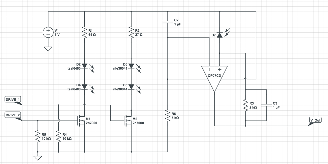
So I realized that it might become a necessity for me to use a transimpedance amplifier for a pulse watch that I intend to make.

Some background:

The pulse watch shoots light at 940 and 660nm at the wrist and picks up the reflected light in a photodiode (https://dk.farnell.com/hamamatsu/s1223/photodiode-pin-to-5/dp/1495587).

Hence why the signal that the photodiode picks up may be diluted and subject to noise, if I don't treat it correctly. The V_Out signal is supposed to go into my Arduinos analog port from which, I (hopefully) can draw a nice pulse curve.

As I'm not an electrical engineer, the primary part that I'm unsure about is the operational amplifier that I inserted into the circuit. I tried to look around for similar applications, but I'm still unsure about the capacitors, and resistors that I've put in there (if the values are correct).

The op-amp I intend to use is this: https://dk.farnell.com/texas-instruments/op07cd/ic-op-amp-low-offset-smd-soic8/dp/9589929?st=OP07

enter image description here

  1. Is this application of the operational amplifier correct, with correct resistor and capacitor values, i.e. will this provide me with a nice low-noise amplified output?

  2. The loop after the photodiode with R3 still confuses me. Is this just to pull V_Out low when no current is flowing?

\$\endgroup\$
2
  • \$\begingroup\$ For one thing, the + and - of your op amp are backwards. Just swap them. \$\endgroup\$
    – wbeaty
    Commented Nov 28, 2018 at 18:50
  • \$\begingroup\$ I realized. Will I be good then? \$\endgroup\$ Commented Nov 28, 2018 at 18:51

1 Answer 1

2
\$\begingroup\$
  1. The front page of the OP07 datasheet says it can run from +/- 3 V supplies, but all specs are for +/- 15 V. And you're only providing 5 V (with a resistor in the negative supply line, why?).

  2. You have your op-amp connected for positive feedback, not negative.

  3. Once you fix the feedback, your circuit will try to produce a negative output voltage proportional to the photocurrent of D7. But the op-amp has no negative supply voltage, so it won't be able to do this.

You need to go back to the drawing board and re-think your op-amp selection, how you power it, and how you make the feedback connection.

Various IC vendors (Analog, TI, etc) have app notes showing how to design an op-amp TIA circuit, so consider using a proven design from one of those.

\$\endgroup\$
6
  • \$\begingroup\$ So what you suggest, is turning the op-amp around, and use another amp like this: dk.farnell.com/microchip/mcp6041-e-p/… ? \$\endgroup\$ Commented Nov 28, 2018 at 18:47
  • \$\begingroup\$ @JeppeChristensen, Fig 1 here shows a reasonable TIA configuration with a single supply. You might want to use your ADC's reference voltage as the input to the non-inverting pin rather than a resistor divider. \$\endgroup\$
    – The Photon
    Commented Nov 28, 2018 at 19:06
  • \$\begingroup\$ I see, but I need more knowledge in order to understand what's going on here. it's extremely intimidating, as I don't have a background in this. \$\endgroup\$ Commented Nov 28, 2018 at 19:44
  • \$\begingroup\$ my.vanderbilt.edu/imaginginstrumentation2016/2016/01/… could something like this work as well? - this, I somewhat understand. \$\endgroup\$ Commented Nov 28, 2018 at 20:02
  • \$\begingroup\$ @JeppeChristensen, yes but you need an op-amp with very good rail-to-rail input and output if you want to be able to measure small optical signals. \$\endgroup\$
    – The Photon
    Commented Nov 28, 2018 at 20:46

Your Answer

By clicking “Post Your Answer”, you agree to our terms of service and acknowledge you have read our privacy policy.

Not the answer you're looking for? Browse other questions tagged or ask your own question.