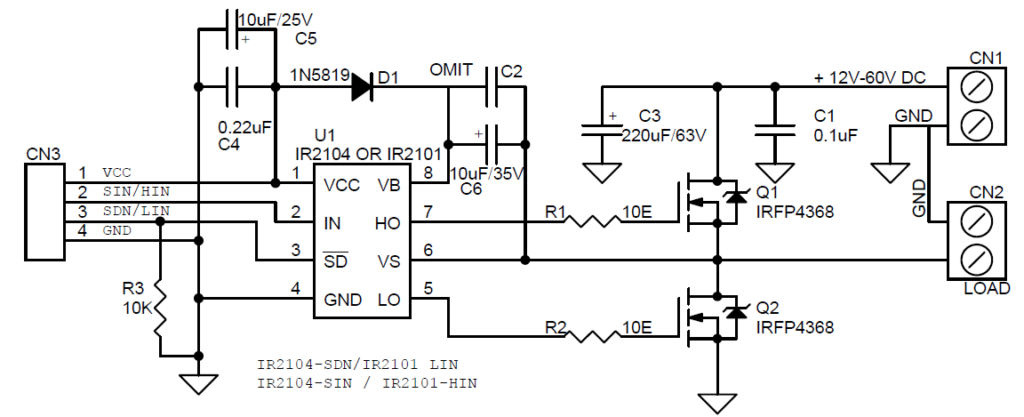
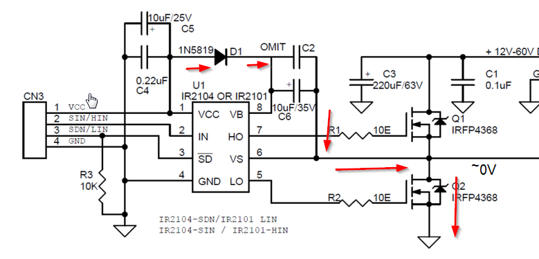
I am trying to build this circuit 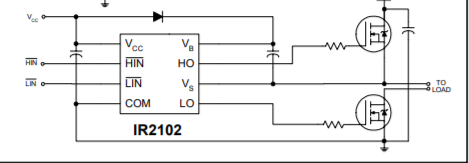 but I don't know how to test it. When I am measuring the voltage on the gate of high side mos is almost 12 volt like VCC. So to speak .. the boostrap circuit isn't working. Dou you have any ideas ?
-
2\$\begingroup\$ The bootstrap circuit will only work if the device is actively switching. \$\endgroup\$– Edgar BrownCommented Nov 28, 2018 at 22:33
3 Answers
Consider this typical circuit from this website:
When Lin is high and thus Q2 is 'on', the output is low and C2/C6 are near ground on the negative side. Vcc then charges the capacitor through diode D1. This provides a voltage source relative to the source of Q1.
When Hin goes high those charged capacitors are used to drive the gate of Q1 high. The charge on the capacitors will eventually be depleted,and Q1 will no longer be able to turn on fully. Some drivers contain a second UVLO for the high side switch, preventing damage which could occur from having the high side transistor partially turned on. The IR2101 does not appear to have that. See, for example, this application note.
So to use this, you should be switching both Lin and Hin actively at a reasonable frequency (typically in the kHz).
-
\$\begingroup\$ UVLO has absolutely nothing to do with the bootstrap voltage, it detects the VCC voltage to prevent driving under conditions where the low side is not driven completely. This is because the failure to provide a low on the external FETs will result in no charge on the bootstrap caps. The circuit would still try to work, but the high side switch FET would potentially burn out due to high dissipation. \$\endgroup\$ Commented Nov 29, 2018 at 17:26
-
\$\begingroup\$ @JackCreasey There is a second UVLO on the high side bootstrap supply that protects the high side MOSFET from inadequate drive voltage. \$\endgroup\$ Commented Nov 29, 2018 at 17:42
-
\$\begingroup\$ Where is the second UVLO? I don't see it in the datasheet. There is a single UVLO that detects when VCC is too low and prevent both channels, but the UVLO has nothing to do with the high voltage being used ...only the VCC serving the chip. \$\endgroup\$ Commented Nov 29, 2018 at 20:40
-
\$\begingroup\$ @JackCreasey Ah, you might be right for that particular case. I don't see it either. This generic app note shows it, and all the IRF drivers I've used have it incorporated. I'll edit the answer. Thanks. \$\endgroup\$ Commented Nov 29, 2018 at 20:53
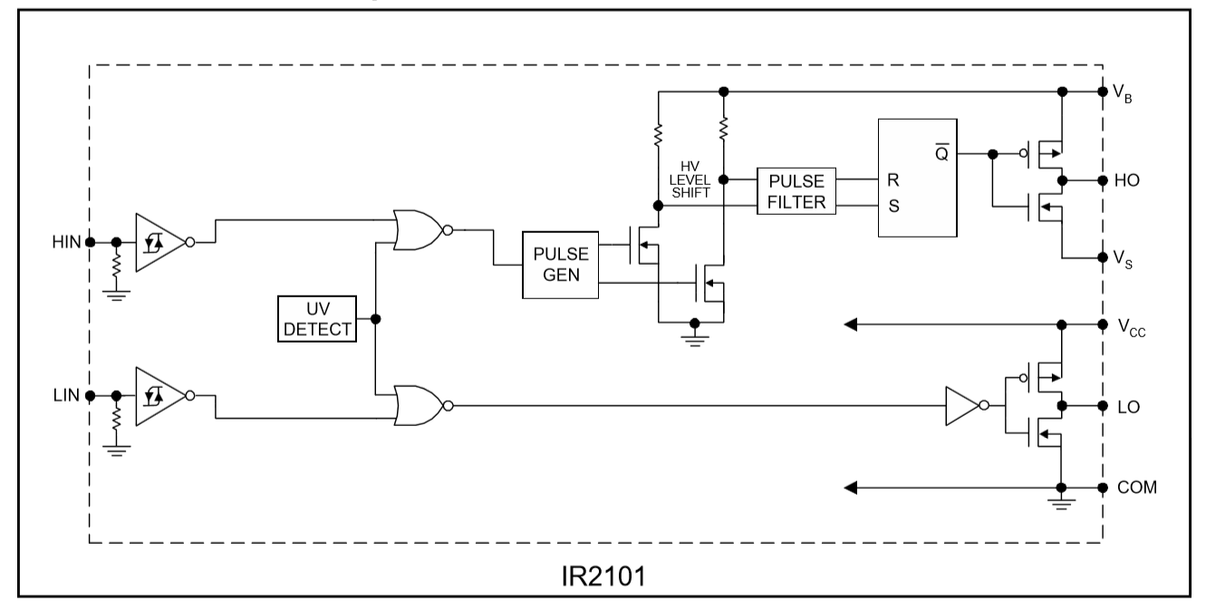
If you read the datasheet for the IR2101 then you can see that the bootstrap capacitor only increases Vb when there is a transition on the output of the external high side FET. So the high side boostrap uses positive feedback to increase the Gate drive voltage and can only work if there is a path to ground to allows the bootstrap capacitor to charge when the external high side driver is off.
So to test the unit you need to drive HIN and VB will ONLY increase if you have a load to allow the cap to charge when the high side switch is off. In other words you need some load to hold Vs lo.
Notice from the internal schematic that LIN has nothing to do with the bootstrap.
-
\$\begingroup\$ My HO is always high no matter if I apply pwm or not... \$\endgroup\$ Commented Nov 29, 2018 at 9:14
-
\$\begingroup\$ @pantarhei I assume you mean HIN …..it has to be toggling to get the bootstrap to work …..in a permanent hi or lo state it does not bootstrap. \$\endgroup\$ Commented Nov 29, 2018 at 17:09
-
\$\begingroup\$ I have two ICs IR2101. With the same configuration on the breadboard. When I apply pwm on HIN one IC has HO pin always 12 volts no matter what and the other one has on HO pin the pwm. Which one is working correctly ? I should mention that if I switch the ICs between them the first one that had HO pin always 12 volts now has a PWM and the other has on HO pin always 12 V. \$\endgroup\$ Commented Dec 1, 2018 at 12:26
-
\$\begingroup\$ @pantarhei Check your breadboard build ...there must be a difference. \$\endgroup\$ Commented Dec 1, 2018 at 16:36
-
\$\begingroup\$ Anyway, but can you tell me which one is the normal behavoir. Always 12 V on HO pin or PWM ? \$\endgroup\$ Commented Dec 1, 2018 at 17:55
@shay yederman
I have used the following configuration, the main purpose was to control a BLDC motor sensorless.
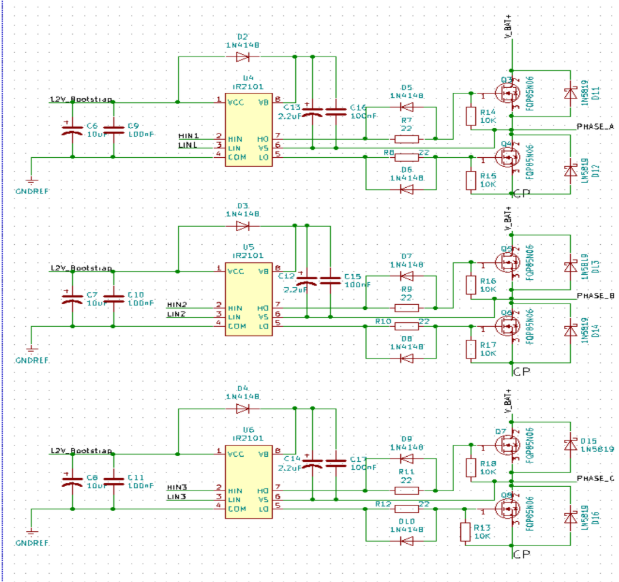
Also some formulas to find out the charge needed and the capacitor value:
QT = QG + (ILKCAP + ILKGS + ILKC + ILKD + IQBS) × tON + QLS
I have used this simplified formula: QT = QG + (ILKCAP + ILKGS + ILKD) × tON + QLS
QG = Total Gate Charge; ILKCAP = Capacitor Leakage Current; ILKGS= Gate-Body Leakage Current; ILKC= Circuit Leakage Current; ILKD = Diode Leakage Current; tON = Switch On Time; QLS = Internal Level Shifter Charge;
It worked for me.

