1
\$\begingroup\$

I'd like to preface with saying that I'm quite new to this.

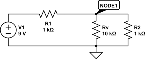
Given emf E = 9 V, and that both resistances are equal, R = 1 kΩ, calculate the voltmeter reading if voltmeter's internal resistance is Rv = 10 kΩ.

So far, I have calculated E * R2 / (R1 + R2) which gives me a result of 4.5V.

But, I'm not sure how to apply the internal resistance of 10k ohms. How does it affect the final result?

Circuit

\$\endgroup\$
4
  • \$\begingroup\$ The voltmeter is in parallel with the right resistor (you should number the components like R1, R2, so we can easily refer to a specific component) \$\endgroup\$ Commented Dec 6, 2018 at 23:39
  • \$\begingroup\$ I updated the image. How does Rv affect the result? \$\endgroup\$
    – alcatraz
    Commented Dec 6, 2018 at 23:41
  • 1
    \$\begingroup\$ Rv is in parallel with R2. So work out the parallel resistance of Rv & R2. Then use that new value in place of R2 in your voltage calculation. \$\endgroup\$
    – Simon B
    Commented Dec 6, 2018 at 23:56
  • \$\begingroup\$ It's called Voltmeter loading. Treat it as a series parallel circuit and solve for R2. \$\endgroup\$ Commented Dec 7, 2018 at 3:17

1 Answer 1

0
\$\begingroup\$

List out what you know from the problem

E = 9 V

R1 = R2 = R = 1 kΩ

Rv = 10 kΩ

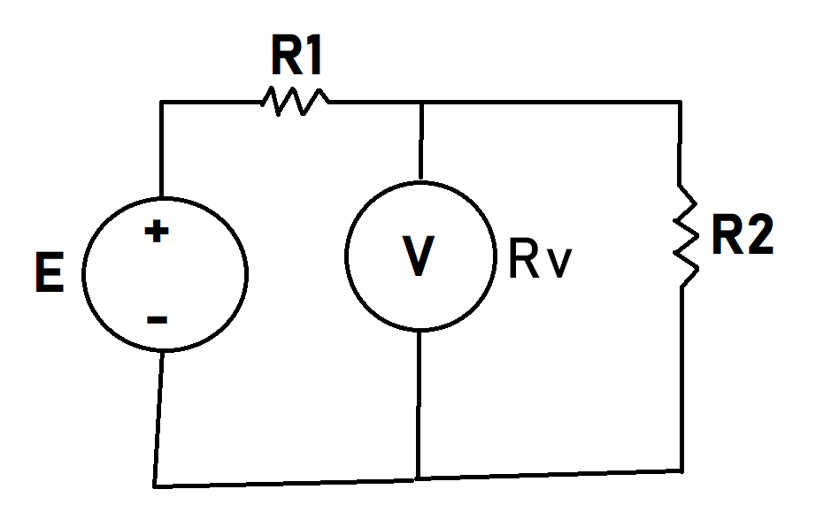
It can help to redraw the circuit to make how you're thinking about it clearer. enter image description here
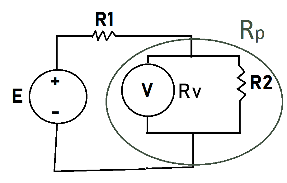
Apply the handy two parallel resister formula

     Rv x R2   10 x 1   10
Rp = ------- = ------ = -- kΩ
     Rv + R2   10 + 1   11

The simplified circuit is now two resisters in series.
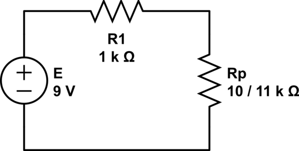
schematic

simulate this circuit – Schematic created using CircuitLab

Apply the voltage division rule

         Rp            10 / 11          10 / 11       10     30
Ep = E ------- = 9 --------------- = 9 --------- = 9 ---- = ---- ~ 4.3 V
       R1 + Rp      1 + (10 / 11)       21 / 11       21      7

Ep will be what the voltmeter (V) will read. This is within 95% of what theory predicts an idealized voltmeter (∞Ω) would have measured (4.5v). Which is not bad considering the voltmeter only has 10 times the resistance of the resisters.

You can check these results in the sites handy Circuit Lab:
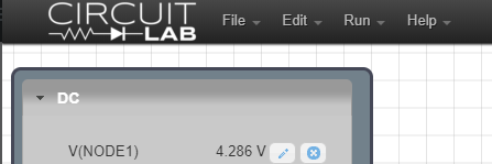
enter image description here

schematic

simulate this circuit

\$\endgroup\$
1
  • \$\begingroup\$ That site's going to be a lifesaver I feel. Thanks! \$\endgroup\$
    – alcatraz
    Commented Dec 7, 2018 at 6:35

Your Answer

By clicking “Post Your Answer”, you agree to our terms of service and acknowledge you have read our privacy policy.

Not the answer you're looking for? Browse other questions tagged or ask your own question.