0
\$\begingroup\$

I'm a total noob on Arduino here, and this is my first project on 16x2 LCD, 4x4 keypad and others. So, the story is, after I uploaded the program for my group's Arduino alarm clock to the Arduino board, the LCD displays black boxes on the first row of the LCD. Plus, when I disconnected the board from my computer and connected the board to a 5V adaptor, the LCD didn't display anything.

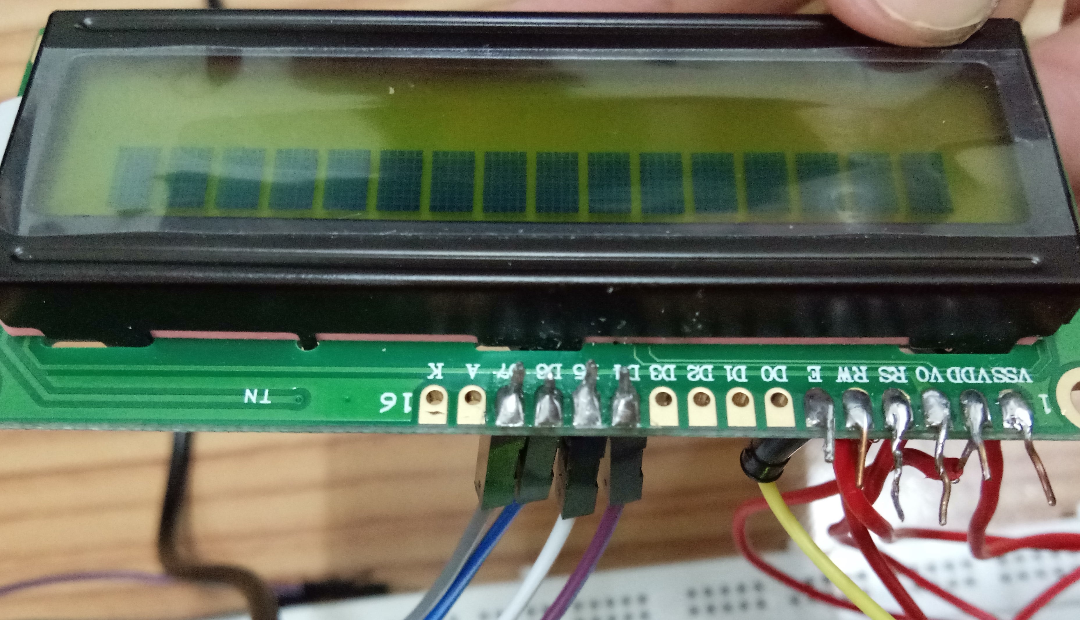
I've already searched the possible causes from the Internet, and mainly they said that either the initialization of the LCD is wrong or there are problems on the soldering. My friend and I concluded that there are no problem with the soldering, but we don't know where the problem is in the program.

The thing is, we didn't have any connection for the backlight of the LCD since we have no potentiometer. I tried to control the contrast and brightness of the LCD by using the Arduino, but I can't understand anything since I'm a total noob.

This is the image of the soldering of the LCD. soldering at the 16x2 LCD
Below is the latest code that we uploaded on the Arduino board. Is there any fault in the program?

    #include <EEPROM.h>
    #include <Keypad.h>
    #include <DS1307.h>
    #include <Wire.h>
    #include <Adafruit_GFX.h>
    #include <LiquidCrystal.h>
    DS1307 rtc(SDA, SCL);
    LiquidCrystal lcd(A3, A2, A1, A0, 5, 4);
    Time t;

    #define buz 3

    int Hor, Min, Sec, h, m, s;
    int ASCII = 48;
    char* tim;
    char* dat;
    const char key = 0;
    char buffer[2];
    const byte numRows= 4;
    const byte numCols= 4;
    char keymap[numRows][numCols]=
    {
    {'1', '2', '3', 'A'},
    {'4', '5', '6', 'B'},
    {'7', '8', '9', 'C'},
    {'*', '0', '#', 'D'}
    };
    byte rowPins[numRows] = {12, 11, 10, 9};
    byte colPins[numCols]= {8, 7, 6, 5};
    Keypad myKeypad= Keypad(makeKeymap(keymap),rowPins, colPins, numRows, numCols);

    void setup() {
    Wire.begin();
    rtc.begin();
    pinMode(buz, OUTPUT);
    lcd.begin(16, 2);
    welcome();

    rtc.setDOW(SATURDAY); //Set Day-of-Week to SUNDAY
    rtc.setTime(10, 54, 0); //Set the time to 12:00:00     (24hr format)
    rtc.setDate(7, 1, 2017); //Day, Month, Year
    }

    void loop() {
    t = rtc.getTime();
    Hor = t.hour;
    Min = t.min;
    Sec = t.sec;
    tim = rtc.getTimeStr();
    dat = rtc.getDateStr();
    char key = myKeypad.getKey();

    if (key == 'C'){
    digitalWrite(buz, LOW);
    EEPROM.write(2, ASCII+6);
    EEPROM.write(3, ASCII);
    }

    if(key == '#'){
    lcd.setCursor(0,0);
    lcd.print("Enter New Time");
    lcd.setCursor(0,1);
    int j =0;
    int i=0;
    while( j<6)
    {
    if(i==2 || i == 5){
    lcd.print(":");
    lcd.display();
    i++;
    }
    key=myKeypad.getKey();
    if(key)
    {
    lcd.print(key);
    lcd.display();
    EEPROM.write(j,key);
    j++;
    i++;
    }
    }
    }

    changealarm();
    checkalarm();
    timedate();
    }

    void checkalarm(){
    if( Hor == h && Min == m)
    {
    delay(3000);
    lcd.setCursor(0,1);
    lcd.print("Hold C");
    digitalWrite(buz, HIGH);
    delay(3000);
    }
    }

    void changealarm(){
    buffer[0]=EEPROM.read(0);
    buffer[1]=EEPROM.read(1);
    h = atoi(buffer);
    buffer[0]=EEPROM.read(2);
    buffer[1]=EEPROM.read(3);
    m = atoi(buffer);
    buffer[0]=EEPROM.read(4);
    buffer[1]=EEPROM.read(5);
    s = atoi(buffer);
    }

    void timedate(){
    lcd.setCursor(0,0);
    lcd.print("Time: ");
    lcd.print(rtc.getTimeStr());

    lcd.setCursor(0,1);
    lcd.print("Date: ");
    lcd.print(rtc.getDateStr());
    delay(3000);
    lcd.setCursor(0,1);
    lcd.print("Alarm: ");
    lcd.print(h);
    lcd.print(".");
    lcd.print(m);
    lcd.print(".");
    lcd.print(s);
    delay(3000);
    }

    void welcome(){
    lcd.setCursor(0,0);
    lcd.print("Welcome");

    lcd.setCursor(0,1);
    lcd.print("To");
    delay(3000);

    lcd.setCursor(0,1);
    lcd.print("TIMeProject");
    delay(3000);
    }
\$\endgroup\$
7
  • 3
    \$\begingroup\$ Before you attempt any more testing, I suggest you trim the excess wire that is not insulated to reduce the possibility of any short circuits... \$\endgroup\$
    – Solar Mike
    Commented Dec 16, 2018 at 15:55
  • \$\begingroup\$ Program code is always singular. "Codes" are what you use to open a keypad lock or to decode a secret message. \$\endgroup\$
    – JRE
    Commented Dec 16, 2018 at 15:59
  • 2
    \$\begingroup\$ Write a simple program that only initializes the LCD and writes a simple text to the display. That will help you figure out if you have a software problem or a hardware problem. \$\endgroup\$
    – JRE
    Commented Dec 16, 2018 at 16:02
  • 3
    \$\begingroup\$ Also, you should get and use a potentiometer for the contrast. The Arduino doesn't output a simple analog signal. "Analogwrite" sends a pulse width modulated signal. It is a bunch of pulses with two states: on (+5V) and off (0V.) \$\endgroup\$
    – JRE
    Commented Dec 16, 2018 at 16:05
  • \$\begingroup\$ To trim excess wire, you want cutters that look like this pair. \$\endgroup\$ Commented Dec 16, 2018 at 18:52

2 Answers 2

0
\$\begingroup\$

The LCD is not being initialized properly. It is probably a firmware or wiring error.

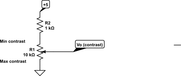
Check that the RW pin is grounded. Connect your pot ELEMENT one side to GND (Vss on the LCD) and one to +5V (Vdd on the LCD) through a 1K resistor.

The pot WIPER goes to Vo on the LCD display.

The 1K resistor is not 100% necessary but it protects the pot if you make a mistake.

schematic

simulate this circuit – Schematic created using CircuitLab


If that doesn't work, check the pin numbers on the Arduino and how it matches to the respective LCD pin numbers very carefully. RW should go to ground and not to the Arduino.


The A and K pins are for the backlight, which may or may not be present. Leave that for now.

\$\endgroup\$
1
  • 1
    \$\begingroup\$ We've desoldered the wires and solder them again to the respective pins on LCD. We've also connected the 10k ohm potentiometer to the Vo of the LCD. I leave out the A and K pin for now. After adjusting the potentiometer, the LCD displays the "Welcome" part. However, after a while, some strange letters pop out. We are not sure what is the problem. \$\endgroup\$ Commented Dec 17, 2018 at 11:23
1
\$\begingroup\$

In general, seeing the boxes like that on these character LCDs often is a contrast issue. As noted in the comments, AnalogWrite generates a PWM pulse train which won't correctly control the contrast. If you can't get a potentiometer, try using two fixed resistors as a voltage divider to try getting closer to a usable contrast level. I'd start with two equal resistors to give 2.5 volts to the contrast pin.

\$\endgroup\$
3
  • \$\begingroup\$ There's only one line of boxes. Can that still be a contrast issue? Were it me, I'd want to see if the boxes don't appear until after the firmware initializes. \$\endgroup\$
    – gbarry
    Commented Dec 16, 2018 at 19:56
  • \$\begingroup\$ Ah. I missed that there was only one row in the photo. This probably discounts it being just contrast. Time to look back at the code \$\endgroup\$
    – DoxyLover
    Commented Dec 16, 2018 at 20:39
  • \$\begingroup\$ I've add a 10k ohm potentiometer and after adjusting a bit, the LCD can display properly again. Thank you! \$\endgroup\$ Commented Dec 17, 2018 at 23:48

Your Answer

By clicking “Post Your Answer”, you agree to our terms of service and acknowledge you have read our privacy policy.

Not the answer you're looking for? Browse other questions tagged or ask your own question.