0
\$\begingroup\$

As you can see on my github https://github.com/mancio/Volante-The-Gamepad I'm designing a gamepad with analog axes and digital touch buttons using pull-up resistors

My pull-up resistor switch works like that:
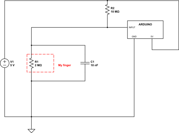
schematic

simulate this circuit – Schematic created using CircuitLab

The 2 MOhm resistor is my dry skin that short the circuit to ground closing the switch. The Idea come from the Makey Makey project https://makeymakey.com and actually works.

I have some issue to fix button flipping. I'm able to partially debounce the switch with with the capacitor, but bigger is the capacitor bigger is the delay of the switch. Total debounce means also too big time delay during switching.

Here you can see my PCB button: one serpentine pad is connected to the input an the other to GND. The finger act as a bridge.

I tried several button design. I wish to improve the pad patterns to reach better on/off performance as a real button NO-switch.

I was thinking to use this formula https://www.allaboutcircuits.com/tools/resistance-calculator to find the resistivity of a component (in this case my finger).

I have some questions:

  • Is not clear to me if L is the length of my skin between the ground and input PAD on my PCB button or how much am I tall.
  • what represent the Area (the rectangle of skin between the pads or the area of my body)
  • how can I know the resistance of my skin in ohm-m (Ω-m) (assuming dry skin worst case scenario)
  • if I print only two big pads with 1 mm distance between them instead of a serpentine I can obtain a better on/off switch.

Thanks very much for help :)

\$\endgroup\$

1 Answer 1

0
\$\begingroup\$

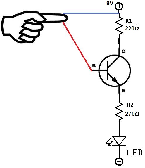
A 10M pull-up is extremely weak. I am not surprised that it keeps flipping - Any resistance lower than around 4.3M will cause the input to be detected as LOW. Board contamination (dust, flux, humidity, etc) can do this. This is an extremely unreliable method to do this, and I wouldn't trust it for a second. Instead I recommend you use a transistor (preferably darlington) to detect the touch. See this page for details (about half way down you'll find a resistive touch sensor example): https://www.electronicshub.org/touch-sensors/

Another example can be found here: http://www.learningaboutelectronics.com/Articles/How-to-build-a-touch-sensor-circuit

enter image description here

These are very basic, but are the heart of this sort of resisitve touch sensor. There are a number of different variants you can use, so google for "resistive touch sensor". I guarantee you'll find one that will work far better for your project.

\$\endgroup\$
4
  • \$\begingroup\$ Sorry I forget to mention that I'm debouncing also by software the button. My question was more focus on the usage of the formula. I cannot immagine how my body can be simplified as a classic cylinder shape resistor as shown in the formula page. \$\endgroup\$ Commented Dec 19, 2018 at 14:05
  • \$\begingroup\$ The calculator you're referring to is designed for a block or wire of copper, aluminum, or other conductive material. It cannot really be applied to a human finger and be expected to be accurate. That's not what the calculator was designed for. So the easy answer is, don't use that formula. Do it right using a transistor \$\endgroup\$
    – DerStrom8
    Commented Dec 19, 2018 at 14:08
  • 1
    \$\begingroup\$ @DerStrom8 How does that first circuit work? The base of the first transistor is permanently pulled to ground. There is no way the transistor can turn on. \$\endgroup\$
    – HandyHowie
    Commented Dec 19, 2018 at 15:04
  • \$\begingroup\$ @HandyHowie HA! I didn't even notice - I was just looking at the transistor part of the circuit. I'll remove that example. \$\endgroup\$
    – DerStrom8
    Commented Dec 19, 2018 at 15:09

Your Answer

By clicking “Post Your Answer”, you agree to our terms of service and acknowledge you have read our privacy policy.

Not the answer you're looking for? Browse other questions tagged or ask your own question.