3
\$\begingroup\$

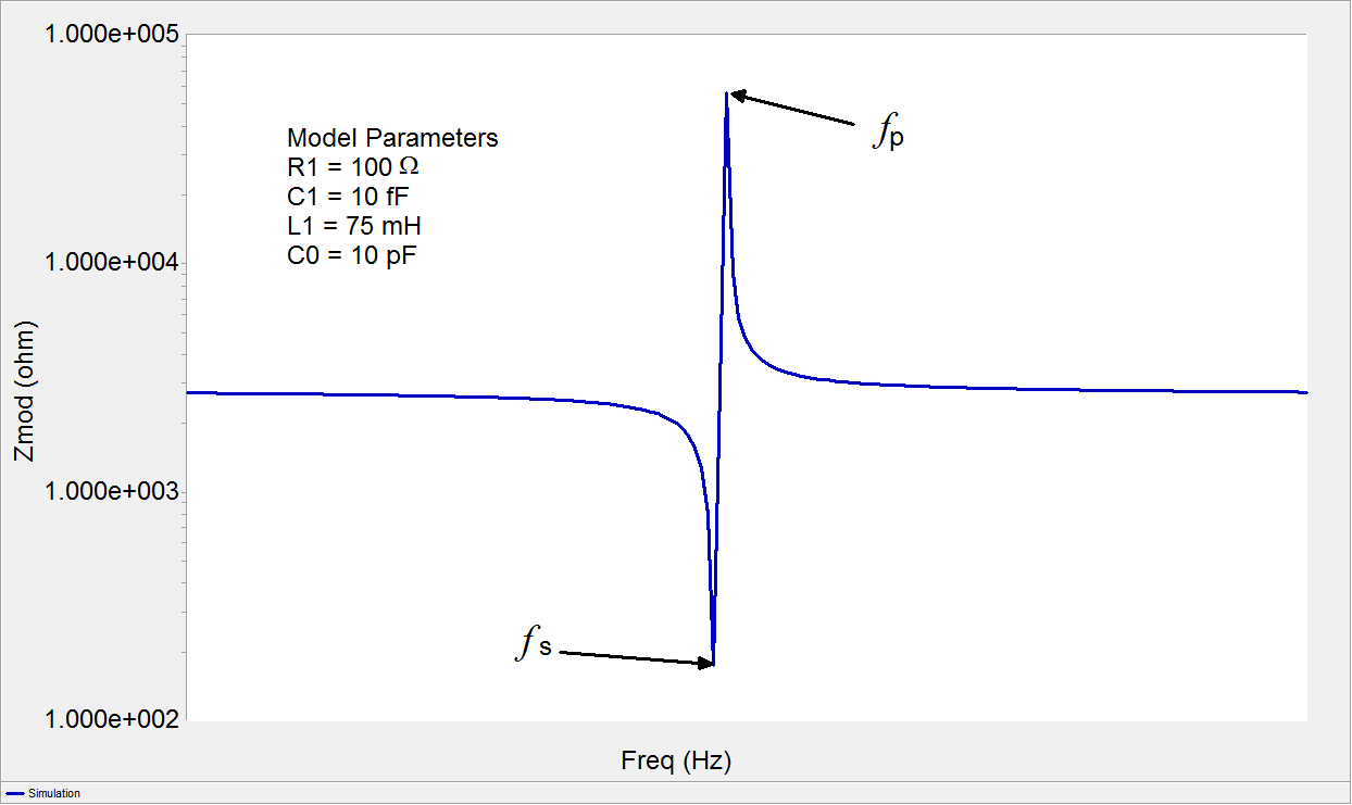
I thought that at the series resonant frequency of a piezoelectric oscillator the impedance of the crystal would be the lowest, and at the parallel resonant frequency the impedance would be the highest. This picture would suggest so:

enter image description here

Clearly at series resonance, the impedance spikes low, and at parallel resonance the impedance spikes high.

But then there are other kind of graphs:

enter image description here

enter image description here

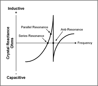
In the first one, apparently positive y-axis indicates inductive reactance, and negative y-axis indicates capacitive reactance. I get the series resonant point: It is the one with the smallest absolute value. But why is the parallel resonant point at somewhere between 0 and the tip of the spike? Shouldn't it be at the tip where the impedance is the highest? And what is "antiresonance"?

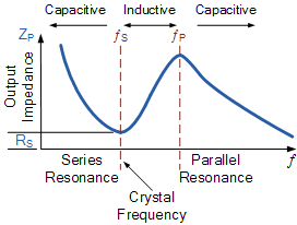
The second picture I find equally confusing. It again seems to plot the absolute value of the impedance. Here the series and parallel points are the lowest and highest, as I would expect, but only in the center region! Clearly if we go to the left, the curve goes up again, indicating there is a frequency for which the impedance of the crystal is higher. And likewise, if we go to the right, it would seem there is a point with a lower impedance. So why aren't the resonant points somewhere on the higher and lower frequencies? Or is there something I've completely misunderstood about resonance?

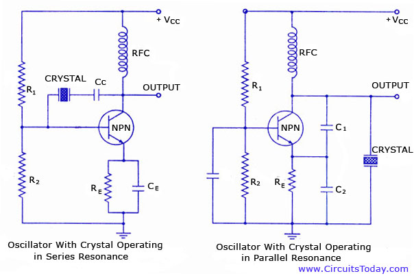
Here is a picture of a crystal oscillator in both series and parallel mode:

enter image description here

On the left, there is an oscillator with the crystal in series mode. The output of the amplifier is connected to the input through the crystal. As the series mode crystal has the smallest impedance at the series frequency, this is the frequency that is filtered from noise by the crystal and fed back to the amplifier input, and therefore the oscillator oscillates at this frequency. This is how I would imagine it to work, but according to the graphs, there should be other frequencies (higher) that can pass the crystal easier. So why doesn't the oscillator oscillate at these frequencies? The same question applies for the parallel oscillator, except this time the impedance is highest for the desired frequency, and it is therefore the one being fed into the amp, with the other frequencies being directed to ground as the impedance is very low for these frequencies.

\$\endgroup\$
2
  • \$\begingroup\$ Google equivalent circuit of a crystal and study the circuit and, if you have a sim try it out for yourself. It should become clearer. \$\endgroup\$
    – Andy aka
    Commented Dec 19, 2018 at 18:58
  • \$\begingroup\$ Graph 1 is the correct response curve. Graph 2:see my description below. Graph 3 should have the ends level out like graph 1, with a slight downward slope inversely proportional to frequency like a capacitor. The rounded peaks as shown are more like you would expect form a low Q device like a piezoelectric beeper. \$\endgroup\$ Commented Mar 8, 2022 at 4:03

6 Answers 6

6
\$\begingroup\$

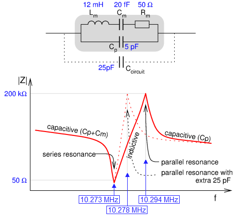
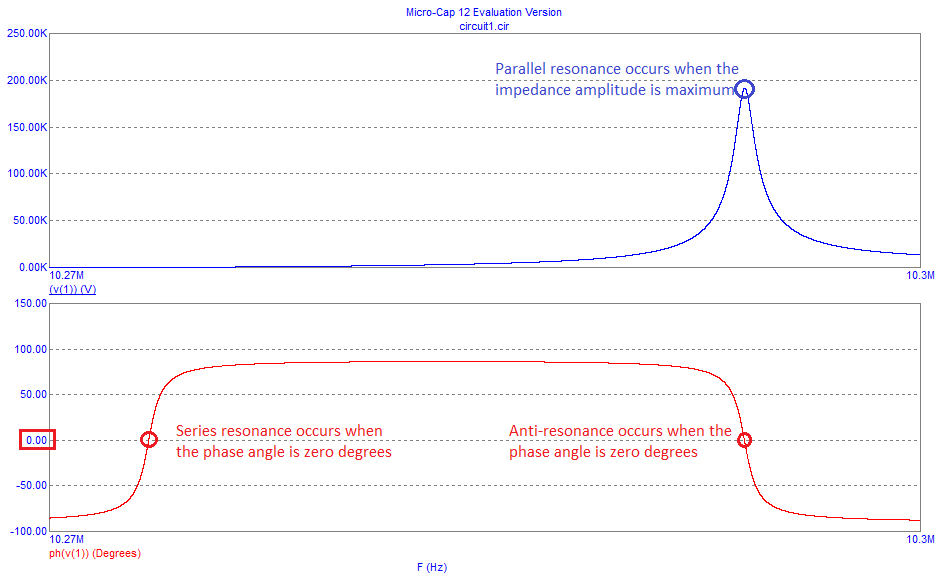
Look at this graph: -

enter image description here

The vertical axis is purely impedance and the parallel impedance coincides with the peak impedance. Adding more parallel capacitance lowers that high-impedance point.

Look at the X-scale - everything happens over a very small frequency range. Some graphs seen on the internet are downright misleading because they don't tell you that what they show is just the X-axis in a small range of a few hertz (for some real crystals).

The parallel resonance is the peak of the magnitude BUT it doesn't have a defined impedance angle (unlike series resonance). Series resonance occurs when \$L_M\$ and \$C_M\$ are nearly cancelling their impedances and we are left with \$R_M\$ in parallel with \$C_P\$ and this is close to zero degrees. I say "nearly cancelling" because to get true 0 degrees phase shift in the impedance there needs to be a slight mismatch.

So, moving on to your 2nd diagram (the one that is possibly seeming to contradict things), there is the anti-resonance point and this corresponds with the phase angle being purely resistive but, in fact it is very high in magnitude. The second diagram only tells you whether the reactance is capacitive or inductive and, possibly misleadingly, gives the impression that overall impedance is comparable with the series resonance case. Not true. Somewhere very slightly displaced from the anti-resonance point is the parallel resonance - it is a peak in magnitude but not at zero degrees.

So, if you were using the crystal as a parallel filter you might naturally choose the parallel resonance point because you wouldn't care too much about the phase angle. This would be the case of the right-hand circuit at the bottom of your question. It is a Colpitts oscillator and the crystal would kill oscillations at anything other than close to parallel resonance.

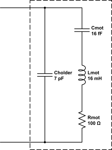
Here's a simulation using the values in the above drawing. A current source of 1 amp was used to excite the model and the frequency range is from 10.27 MHz to 10.3 MHz: -

enter image description here

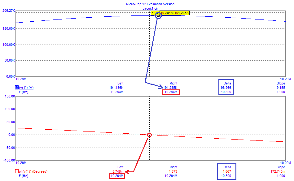
And here's a close-up the the parallel/anti resonance area: -

enter image description here

I've positioned left and right cursors as follows: -

  • Left corresponds with zero degrees phase angle (-0.005748 degrees is as near as I can manipulate this)
  • Right is positioned to correspond with the impedance maximum peak of 191.285 kohm

Of importance is the delta measurements displayed (inside blue boxes) - they accurately calculate the difference in frequency between left and right cursors and show the delta to be 10.809 degrees i.e. anti-resonance and parallel resonance are displaced by about 11 Hz.

\$\endgroup\$
6
  • \$\begingroup\$ You say the angle of parallel resonance is not defined, why is that? I thought that in parallel resonance also, the reactances of the inductor and the capacitor are equal and opposite. So if the move to the right from the series resonant point, the series "arm" in the equivalent model becomes inductive. Then the parallel resonant point occurs when the capacitance in parallel to the series "arm" is equal in magnitude but opposite in phase.. \$\endgroup\$
    – S. Rotos
    Commented Dec 19, 2018 at 19:50
  • \$\begingroup\$ Not quite; the antiresonant point is when the angle of impedance is purely zero degrees but, this doesn't quite correspond with the impedance being at a true magnitude maximum. I would advise you to run a sim and see this for yourself. \$\endgroup\$
    – Andy aka
    Commented Dec 19, 2018 at 20:01
  • 1
    \$\begingroup\$ That would be true for a simple parallel LC circuit but it’s not true with a crystal and it’s not true for its equivalent circuit. It’s not even true with some single RLC low pass filters ie resonant peak only ever corresponds with the “archetypal” phase shift when Q is infinite. For a crystal Q is of course very very large and the difference between anti resonance and parallel resonance is usually measured in parts per million. \$\endgroup\$
    – Andy aka
    Commented Dec 19, 2018 at 20:48
  • 2
    \$\begingroup\$ Mr Rotos We are looking at a 3rd order component and not a 2nd order one. This is why it has both series and shunt resonance. But more important for frequency tuning is not the peak spike but the exact phase shift needed to oscillate. with added Caps that add an RC phase shift to tune the frequency a few xx ppm at 180 deg for P and 0 deg for S. Making it a 4th or 5th order filter. \$\endgroup\$
    – D.A.S.
    Commented Dec 19, 2018 at 20:49
  • 1
    \$\begingroup\$ Run AC simulations (should be very quick to run) and examine how the gain of the amplifier and the bandwidth of the amplifier affect the frequency of oscillation. And examine how the small extra phaseshift can be your friend or your enemy. \$\endgroup\$ Commented Dec 20, 2018 at 4:35
2
\$\begingroup\$

Here's a hopefully close to accurate schematic of a equivalent circuit of a crystal with a series-resonant frequency of 10MHz or so. Someone may object to my numbers, which is fine because I pulled them out of my head, and it's been a while since I've designed an oscillator. I stress the "equivalent circuit" part because all of the components labeled 'mot' are due to the crystal's motion and piezoelectric effect.

Each of those three impedance plots you show are different views of the same thing. The top plot is a logarithmic plot of the absolute value of the impedance over a wide range. The middle plot is of the reactive part of the impedance, while the bottom plot is a "close up" plot right around where the thing will oscillate. They're all different views of the same thing.

When you design an oscillator for a series-resonant crystal, you're trying for an oscillator that may work at more or less the design frequency if you replaced the crystal with a short circuit -- the crystal just makes sure that the "short circuit" in question is exactly at the crystal frequency.

When you design an oscillator for a parallel-resonant crystal, you're using the fact that above the resonant frequency, the crystal looks inductive. In a parallel-resonant circuit, the oscillation frequency is determined both by the crystal and by the total parallel capacitance -- this is why a parallel-resonant crystal is specified for a given frequency and capacitive load.

Dunno if this helps. The discussion is necessarily short -- there's entire books out there written just for crystal oscillators, and all of the oscillator books I've seen have at least one chapter devoted just to crystal oscillators. There's no way to cover all the material just in one Stackexchange post.

schematic

simulate this circuit – Schematic created using CircuitLab

\$\endgroup\$
1
\$\begingroup\$

A crystal is not a simple single mode RLC resonance. The crystal itself has a desired resonance governed by its mass, spring constant and damping. You can convert that to an equivalent RLC circuit. That RLC circuit is then in parallel to the electrical capacitance formed by the electrodes. At slightly above the crystal free resonance the crystal reactance is inductive. That inductance combined with the lead capacitance and also the external circuit capacitance forms a parallel LC resonance (also called an anti-resonance).

\$\endgroup\$
0
\$\begingroup\$

Some papers claim TOO MUCH gain will prevent oscillation. That is wrong IMHO. What occurs, to make that claim, is the amplifiers used to provide huge gain also have very low Rout, and that low Rout prevents the needed extra phaseshift.

The first paper I saw on that topic, from the 1970s about how the Swiss watch industry was able to produce 200 nanoAmpere 32,768 Hertz XTAL oscillations, claimed TOO MUCH transconductance was the problem. Again, in using CMOS as the amplifiers, the CMOS inverter amplifier would have LOW Rout, and the phase shift would be slightly off.

\$\endgroup\$
0
\$\begingroup\$

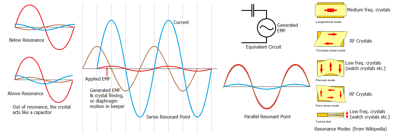
I will put this as a separate answer to clarify to more confusing bits. Firstly, the series resonant point: The current is the vector sum of the applied emf - the generated emf (forward emf, which is negative phase) ÷ the reactance of the capacitive coupling between the crystal and it's electrodes, like a + & - 15V power supply, where the total voltage is + 15 -(-15)=30V, but the phase is shifted forward by 90 deg., by the leading power factor of a capacitor.

At the series resonant point, the vector sum is at -90 Deg., which means, the generated emf is slightly more, (because the small applied emf is at 0 deg.). The Anti-Resonance in graph 2 is shown at the center of the anti resonance mode, where the phase of the vibration is at near -180 degrees.

\$\endgroup\$
0
\$\begingroup\$

In graph 2, where it says parallel resonance, appears to mark the start of parallel resonance rather than the peak, and the Anti-Resonance, the middle of the parallel resonant peak, where the phase of the vibration is reversed by more than 90 degrees. The sudden switch from high impedance inductive to high impedance capacitive is confusing, it is high all the time, but looks like it is going from high to low, but is actually just crossing the border from one type of impedance to another during the high impedance peak.

When I was researching why piezoelectric devices have parallel & series resonant points, like the little native guy in "The Gods Must Be Crazy", I received a gift from the goddess of electricity, Electra. A faulty electronic beeper appeared on my desk.😁 It was just what I was looking for, with a feedback electrode to drive the transistor. I could monitor applied and generated emf independently.

The reason for the 2 points is that the phase of the vibration changes as it goes through resonance, like when you swing a weight on a string, then raise the frequency of your hand. It starts to swing backwards (probably because it is being dragged along at a slightly higher frequency than it is trying to resonate at).

The diaphragm of a beeper moves backward when a +ve polarity is applied, but generates a -ve voltage (forward emf), and vice versa, which adds to the applied emf, increasing the current, especially when it starts to resonate. At the series resonant point, the vibration, and (forward emf) lags about 90 deg. The current is shifted forward 90 deg. by the capacitance between the charge in the crystal and the plates, putting it in phase with the applied emf. The amplitude of the resonance increases with applied current. Very little emf is required, (like a series tuned circuit). As the frequency is raised, the phase of the vibration almost completely reverses, changing the forward emf to back emf. The amplitude is now controlled by the applied emf: BACK EMF≈APPLIED EMF. I measured about a -162 deg. ф shift with the beeper, just slightly short of -180, so it could be dragged along by the applied emf instead of being exactly opposite, which would absorb no energy, just increase the stiffness and resonant frequency a bit. The higher voltage, at near -180 deg. would help raise the resonant frequency to the second point. The resonant frequency of a piezoelectric transducer is a bit lower with the i/p shorted, than with it o/c, where the generated emf tries to make the ceramic disc bend the other way, effectively increasing it's stiffness. Above the resonant frequency, the ф became virtually -180 degrees. The parallel point ф shift is much closer to -180 deg., and the points much sharper and closer together with a crystal, due to it's much higher Q. enter image description here

\$\endgroup\$
2
  • \$\begingroup\$ Please provide a citation or link for the graphic you copied into your answer. The policy for this site is to always give credit to the original creator. \$\endgroup\$ Commented Mar 4, 2022 at 17:10
  • \$\begingroup\$ @Elliot Anderson It's written on the diagram in brackets under the picture of the resonance modes. It was from Wikipedia Crystal Oscillator. The rest was my creation. \$\endgroup\$ Commented Mar 6, 2022 at 3:16

Your Answer

By clicking “Post Your Answer”, you agree to our terms of service and acknowledge you have read our privacy policy.

Not the answer you're looking for? Browse other questions tagged or ask your own question.