I have a lattic X03LF starter board with 6900C FGPA. There are eight LED available on this board and a push button.
The goal of my code is to design a 8 bit counter that increments whenever a button is pressed. Also there is another button available that is used for resetting the device.
Since the led work on active low signal, i have the counting start from 0xFFh, 0xFEh, 0xFCh...
Below is the design module for the counter,
module led_counter_starter_kit(
output reg [7:0] led_out,
input sw_n,
input reset_n,
input clk,
output [7:0] cur_st,
output [7:0] nex_st
);

reg [7:0] current_state;
reg [7:0] next_state;

parameter S0 = 8'hFF;
parameter S1 = 8'hFE;
parameter S2 = 8'hFC;
parameter S3 = 8'hF8;
parameter S4 = 8'hF0;
parameter S5 = 8'hE0;
parameter S6 = 8'hC0;
parameter S7 = 8'h80;

always @(posedge clk)   begin
    if (~reset_n)
        current_state <= S0;
    else
        current_state <= next_state;
end // always @(posedge clk)

always @(posedge clk) begin
    case (current_state)
        S0: begin
            if (~sw_n) begin
            next_state <= S1;
            led_out <= S0;
            end
            else begin
                next_state <= S0;
                led_out <= S0;
            end
            end

        S1: begin
            if (~sw_n) begin
            next_state <= S2;
            led_out <= S1;
            end
            else begin
                next_state <= S1;
                led_out <= S1;
            end
            end

        S2: begin
            if (~sw_n) begin
            next_state <= S3;
            led_out <= S2;
            end
            else begin
                next_state <= S2;
                led_out <= S2;
            end
            end

        S3: begin
            if (~sw_n) begin
            next_state <= S4;
            led_out <= S3;
            end
            else begin
                next_state <= S3;
                led_out <= S3;
            end
            end

        S4: begin
            if (~sw_n) begin
            next_state <= S5;
            led_out <= S4;
            end
            else begin
                next_state <= S4;
                led_out <= S4;
            end
            end

        S5: begin
            if (~sw_n) begin
            next_state <= S6;
            led_out <= S5;
            end
            else begin
                next_state <= S5;
                led_out <= S5;
            end
            end

        S6: begin
            if (~sw_n) begin
            next_state <= S7;
            led_out <= S6;
            end
            else begin
                next_state <= S6;
                led_out <= S6;
            end
            end

        S7: begin
            if (~sw_n) begin
            next_state <= S0;
            led_out <= S7;
            end
            else begin
                next_state <= S7;
                led_out <= S7;
            end
            end

        default: next_state <= S0;

        endcase // current_state
    end


/*always @(posedge clk) begin
    if (~reset_n)
        led_out <= S0;
    else begin
        case (current_state)
            S0: led_out <= S1;
            S1: led_out <= S2;
            S2: led_out <= S3;
            S3: led_out <= S4;
            S4: led_out <= S5;
            S5: led_out <= S6;
            S6: led_out <= S7;
            S7: led_out <= S0;
        endcase // case(current_state)
    end

end // always @(posedge  clk)*/

assign cur_st = current_state;
assign nex_st = next_state;


endmodule // led_counter_starter_kit
and the test bench for this design is below:
`timescale 1s / 1s
`include "led_counter_starter_kit.v"

module starter_kit_counter;
    reg clk;
    reg sw_n;
    reg reset_n;
    wire [7:0] led_out;
    wire [7:0] cur_st;
    wire [7:0] nex_st;

    initial begin
        clk = 1'b0;
    forever begin
        #1 clk = ~ clk;
        end
    end

led_counter_starter_kit Test (.led_out(led_out),
                              .sw_n(sw_n),
                              .reset_n(reset_n),
                              .clk(clk),
                              .cur_st(cur_st),
                              .nex_st(nex_st)
                              );

    initial     begin

    @(posedge clk)      reset_n = 1'b0; sw_n = 1'b1;
    @(posedge clk)      reset_n = 1'b1; sw_n = 1'b0;
    @(posedge clk) ;
    @(posedge clk)      sw_n = 1'b0;
    @(posedge clk) ;
    @(posedge clk) ;
    @(negedge clk)      sw_n = 1'b1;
    @(posedge clk) ;
    @(posedge clk) ;
    @(posedge clk) ;    sw_n = 1'b0;
    @(posedge clk) ;
    @(posedge clk) ;
    @(posedge clk) ;    sw_n = 1'b1;
    @(posedge clk) ;
    @(posedge clk) ;
    @(posedge clk) $finish;


    end

endmodule
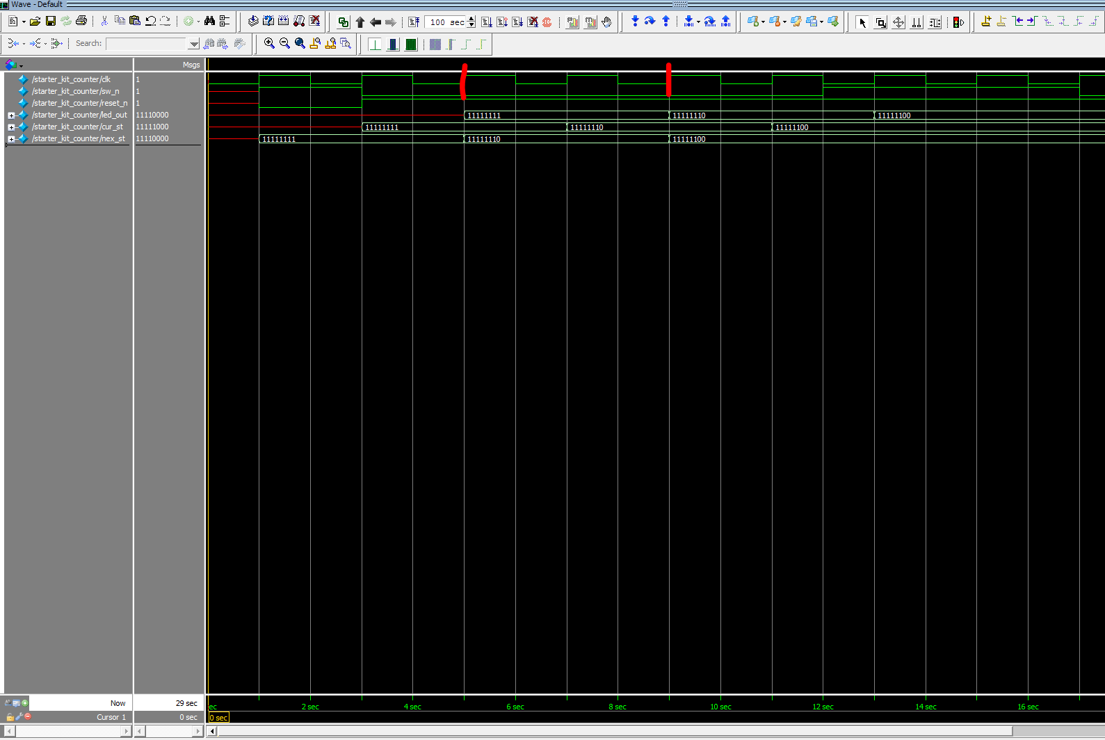
The problem i am running is that the counter is increments after every two cycle of clock period instead after first period.
Here is the snapshot from Model Sim,

update: 12/20/2018
Edited code:
always @(sw_n, current_state) begin
    case (current_state)
        S0: begin
            if (~sw_n) begin
            next_state <= S1;
            led_out <= S0;
            end
            else begin
                next_state <= S0;
                led_out <= S0;
            end
            end


always @(sw_n, current_state)is technically correct, but a better solution would be to use auto-sensitivityalways @*. That way if the reference signals every change, you don't have to remember to add/remove it from the sensitivity. Separately, it is recommended use blocking assignment (=) for combiantional logic. Non-blocking assignment (<=) should be used with assigning synchronous logic. \$\endgroup\$