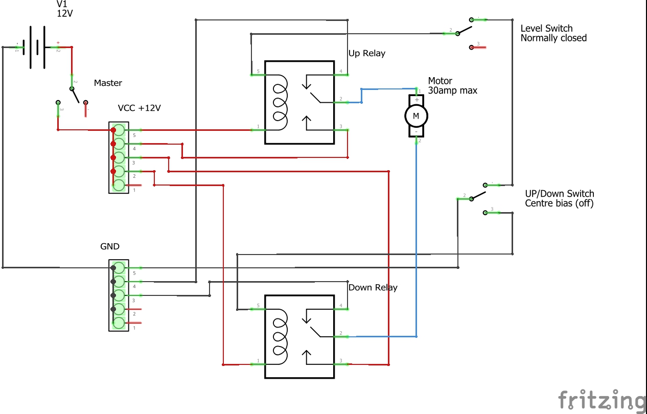
I am designing a circuit to replace a problematic computer controlled raise/lower operation for our mobile home bed. The bed uses a 30 amp DC motor (similar to a wiper motor) and simply reverses the polarity to raise/lower the bed. Quite simple really. There is a limit switch that cuts power when the bed hits an upper limit (thereby opening the normally closed switch) and a master on/off switch controlling the main power supply from a vehicle battery.
I am confident the circuit will work fine however I would like to place an LED in the circuit somewhere to indicate when the limit switch has been activated i.e to light when the limit switch is open.
I have looked at How to create a circuit to turn off LED when switch is "ON" and turn on when "OFF" but this and other answers I can find do not have a relay or other similar load attached to the circuit so I'm unsure how to proceed.
I am considering simply bridging the level limit switch with an LED and appropriate value resistor figuring that with the switch open current will flow through the LED/resistor lighting it. With the switch closed currect will flow through the closed switch instead (path of least resistance) turning the LED off. However I am unsure of the effect the relay will have on the LED when the switch is open. Will it (in effect) try to use power through the LED/resistor thereby burning them out?
Would appreciate some tips/comments/suggestions please.

