5
\$\begingroup\$

Firstly, I'm not from electronics background so my knowledge is limited in this area.

Target System - I am looking to build/ extend the range of 125khz RFID reader upto 1 meter (~ 3ft) to be captured while walking through a gate detector (kind of like two pillar antenna in pic below).

enter image description here

Reason: Commercial gate readers are way too costlier to implement so am looking to build my own.

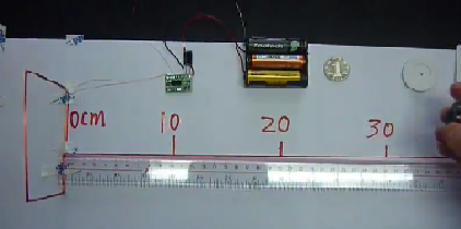
Current State - The below current 10x10cm loop antenna provides me a range upto (~1 ft).

enter image description here

Question: How do i design an Antenna in such a way it has a read range of 5 - 6 feet (throughout the height of pillar) and having read distance up to 3 feet (distance where the tag is presented)? Here the read range is as important as the read distance.

Considerations:

  1. Going for a RF Gate Antenna (the ones you find in clothing store) and plug & play with RFID reader?
  2. Increasing the size/ length of the antenna coil but maintaining the same inductance.
  3. Adding multiple small antennas (like an Array) across the length of the pillar.
  4. Making a dual loop antenna to cover the broader range.

Any help would be appreciated towards moving from my current state to target? I prefer to stick with 125 Khz LF frequency range.

Many thanks!

\$\endgroup\$

2 Answers 2

2
\$\begingroup\$

LF RFID at 125 kHz uses magnetic fields to power tags and load modulation to communicate with them. Your reader does not appear to be powerful enough to generate a magnetic field that has sufficient strength. You need to consider a reader that can supply more current to the antenna or some way to boost it.

Look for a "long range" reader (RFID industry term) for a better solution. The small RFID reader boards are "proximity" (industry term) devices that are only designed to work at close range, such as with a handheld.

You do not mention the tag size which also has an effect. A larger one would increase read range. Tiny glass tags have short range even with powerful readers.

Orientation of the tag to the antenna also affects the read range. If your application could allow the tag to be point in any direction you will definitely need a more powerful reader to detect them at a non-optimal orientation.

With FDX, the tag increases and decreases the resistance (shorts) across its internal coil to cause slight changes in the reader antenna voltage to communicate the 1's and 0's (load modulation). A tiny tag does not put a lot of load to an antenna with a weak magnetic field that is 1m away.

Make sure the antenna is properly tuned. The magnetic field strength, current consumption and read range are highest when in tune.

Good luck!

\$\endgroup\$
2
  • \$\begingroup\$ thanks much! this is useful. I would firstly go for a powerful reader which can supply more current. On the tag, i am planning to use "Access Card" type tag (the one with coil antenna). Any specific suggestion on the Antenna design to cover 5 ft range and 3 ft distance? Or with the powerful reader Do I just have to make it a big rectangle loop antenna (like the one i shown in above pic)? \$\endgroup\$
    – shafir
    Commented Jan 2, 2019 at 11:17
  • \$\begingroup\$ The R in RFID stands for radio but LF RFID is primarily near field inductive power transfer. A strong oscillating magnetic field is needed to charge the tag at a distance and a sensitive loop is needed to detect the small changes in antenna voltage to read the returned message. The same antenna needs to suit two different goals. Antenna design is primarily trial and error. But a small circuit board powered by a few volts is not going to have enough oomph to create a strong field. Another tip is to wind the coil with evenly spaced wires like guitar strings. \$\endgroup\$
    – Warren
    Commented Jan 3, 2019 at 23:41
-1
\$\begingroup\$

In RF electronics particularly when it comes to range is very trial and error, you could try building two separate loop antennas not electrically connected to anything, one slightly larger and one slightly smaller, and placing the larger one behind the main antenna in multiples of one quarter of the wavelength of the trans mitted frequency, and mounting the smaller loop an equal distance in front of the main loop, the actual sizes of the two new antennas you will just haft to experiment with. The wavelength at 125khz is 2400 meters, a multiple of one quarter of that is approximately 29 (about 1 foot) centimeters, if you find it to be too large to be practical you can always halve that distance, another way would just be to increase actual RF transmit power and receive sensitivity possible by using op amp circuits. But once again its trial and error you just need to try combinations of these to get optimum range.

\$\endgroup\$
1
  • \$\begingroup\$ The OP will be in near field; not sure wavelength has much effect here. Phaseshifts???? \$\endgroup\$ Commented Jan 1, 2019 at 22:43

Your Answer

By clicking “Post Your Answer”, you agree to our terms of service and acknowledge you have read our privacy policy.

Not the answer you're looking for? Browse other questions tagged or ask your own question.