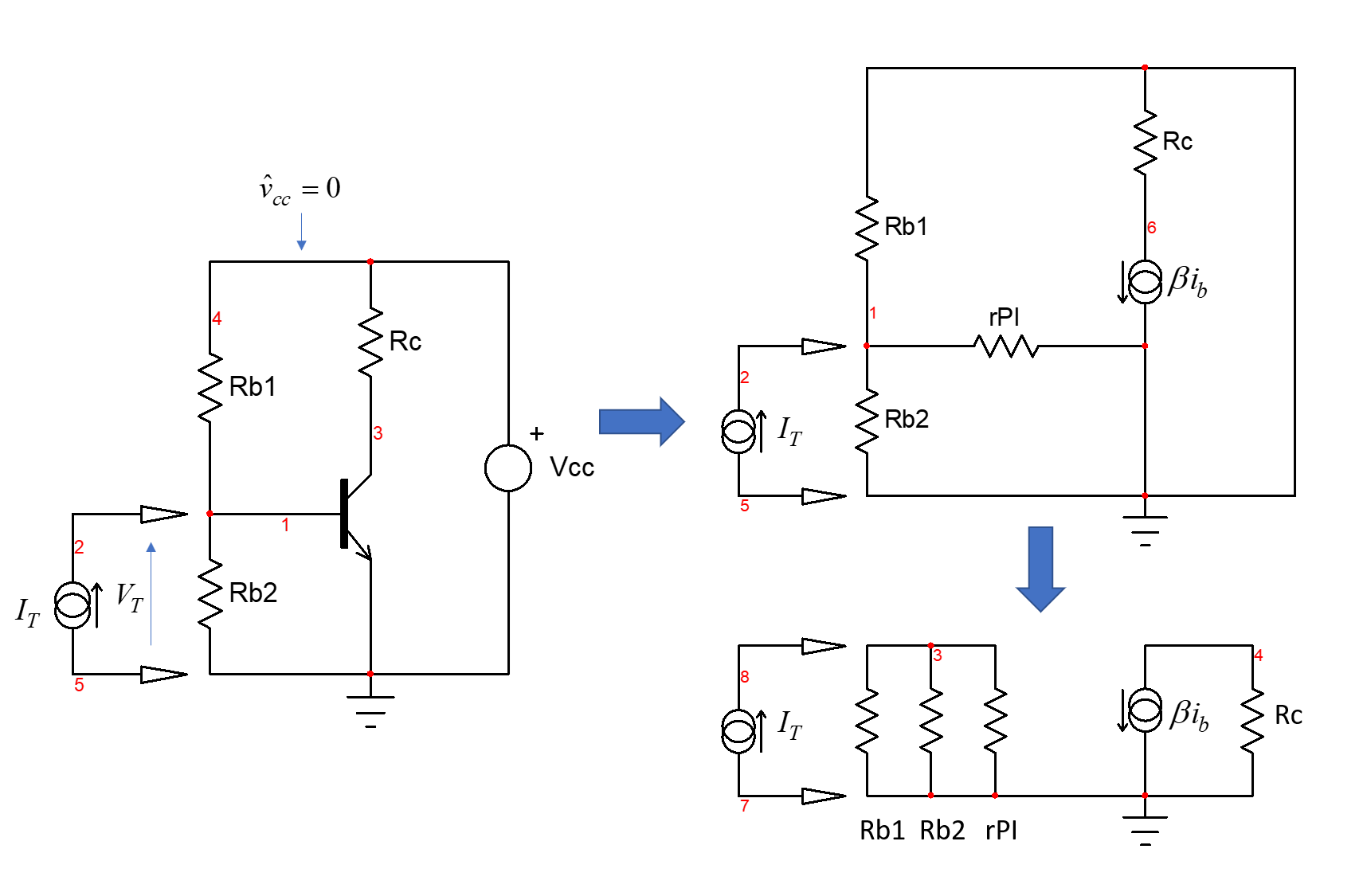
When calculating the input impedance of a voltage divider biased BJT common emitter amplifier, we calculate the parallel resistance of the bias resistors and the emitter resistance. But why do we consider both bias resistors? Looking from the amplifier input (the transistor base), the other resistor leads to the voltage source, while the other leads to ground. Shouldn't we only consider the one that leads to ground? Why would any of the input current go to the voltage source/battery?
-
1\$\begingroup\$ electronics.stackexchange.com/questions/298560/… \$\endgroup\$– G36Commented Jan 4, 2019 at 18:52
-
\$\begingroup\$ Because in"small signal analysis" or AC analysis, both supplies are considered 0V. So they ARE in parallel. In practice. the big supply decoupling capacitor guarantees that Vs has an AC component of 0V. \$\endgroup\$– user16324Commented Jan 4, 2019 at 21:19
2 Answers
When you determine an input impedance (which is a transfer function), you install a test generator (the stimulus) \$I_T\$ across the connecting ports and you determine the response voltage \$V_T\$ collected across the current source terminals. This configuration is called a DPI or driving point impedance as described by the fast analytical circuits techniques or FACTs as described in my book on the subject. The circuit below shows the configuration for the bipolar amplifier you described:
When you do that, you imply that the source supplying your circuit is uncorrelated with the stimulus. It means that if you sweep the input impedance with \$I_T\$, you won't see any ripple over the \$V_{cc}\$ rail supplied by a perfect dc source (0 output impedance). The small-signal amplitude of the \$V_{cc}\$ rail is thus 0 V during the analysis and the source can be replaced by a short circuit for the dynamic analysis. You can also imagine an infinite decoupling capacitor from the \$V_{cc}\$ rail to ground perfectly decoupling the rail during the analysis. As the drawing shows, when the source is shorted, the biasing resistances naturally come in parallel.
-
\$\begingroup\$ Thanks. I found what I searched for in 2 hours. Nobody explained as you.! Diagrams show everything. I understood. Thanks. \$\endgroup\$– upaliCommented Nov 16, 2021 at 16:41
-
\$\begingroup\$ Hey, glad to read this! The secret lies in re-drawing sketches as often highlighted by jonk in his numerous contributions. \$\endgroup\$ Commented Nov 16, 2021 at 21:34
It would be better if you provide the schematic drawing.
When calculating the input resistance, all independent source must be turned off. So, the voltage source is connected to the ground. The resistor that connected to the voltage source is grounded now. That is the reason that you have to consider both bias resistors. Now, those resistors are in parallel.
-
\$\begingroup\$ Your answer makes me more understand. Thanks. \$\endgroup\$– upaliCommented Nov 16, 2021 at 16:42
-
\$\begingroup\$ What about the dynamic resistance of the B-E-path? Did you forget it? Therefore, the independent (supply) must NOT be turned off! In contrary - the input resistance of such a circuit is measured/calculated under full operating conditions. Nevertheless ffor signal voltages applied to the base node., the supply voltage (with zero internal source resistance) acts like a short to ground. Hence, both resistors R1 and R2 are considerd to be grounded - as far as signal voltages are concerned. \$\endgroup\$– LvWCommented Oct 25, 2023 at 6:28

