My aim is to design a pid - motor controller in simulink, and i also have to use h-bridges and PWM generator. The motor is a single phase dc-motor. And the aim is to control the speed. The reference signal contains the desired speed interms of volts.
. before i started designing the pid i simply connected the output port of (abs) to the controlled voltage source without adding the summing block and the feedback blocks. The output matched the signal and it looked pretty good. But the aim was to use pid control with feed back so i assembled the system as shown above. Here is where the problem comes in...
Problems:
When i added the summing block and the pid i got the error algebraic loops which i " corrected " it by going to simulation/ configuration / diagnostics/ and making the error sign to none.
The real problem actually is at my reference and my output. To make it clearer, here is another picture: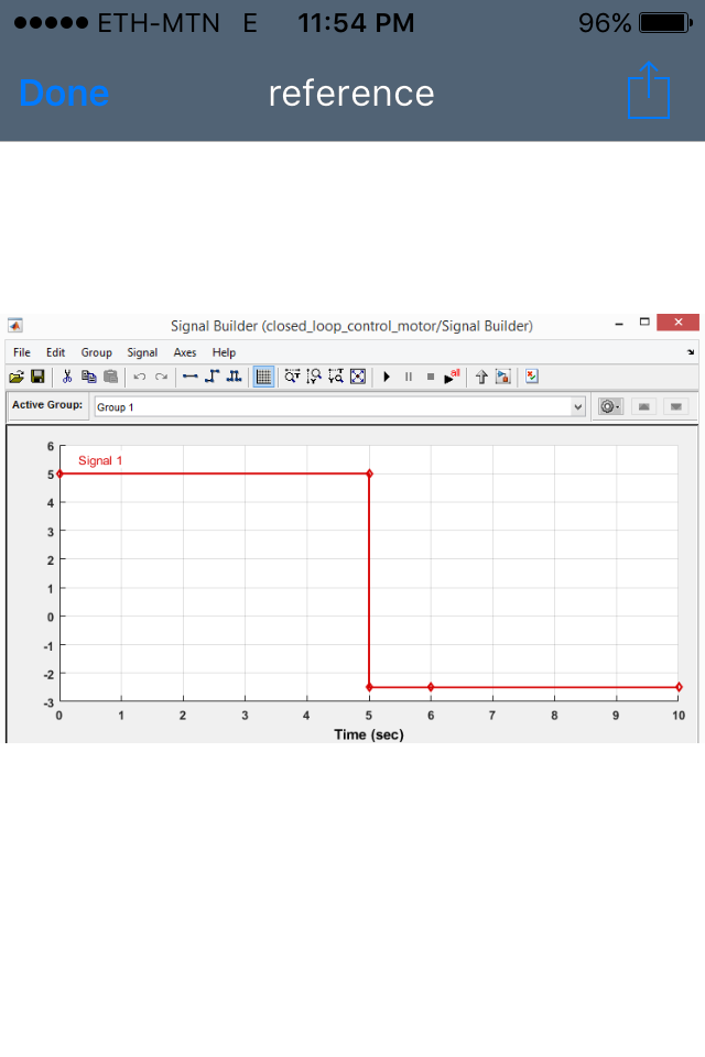
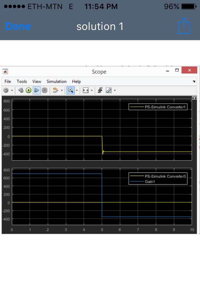 We can see that that the output of the speed is zero for the first 5 seconds which should actually be somwhere about 700. The weird thing about this is i tried it with a different signal reference and look at what happens.
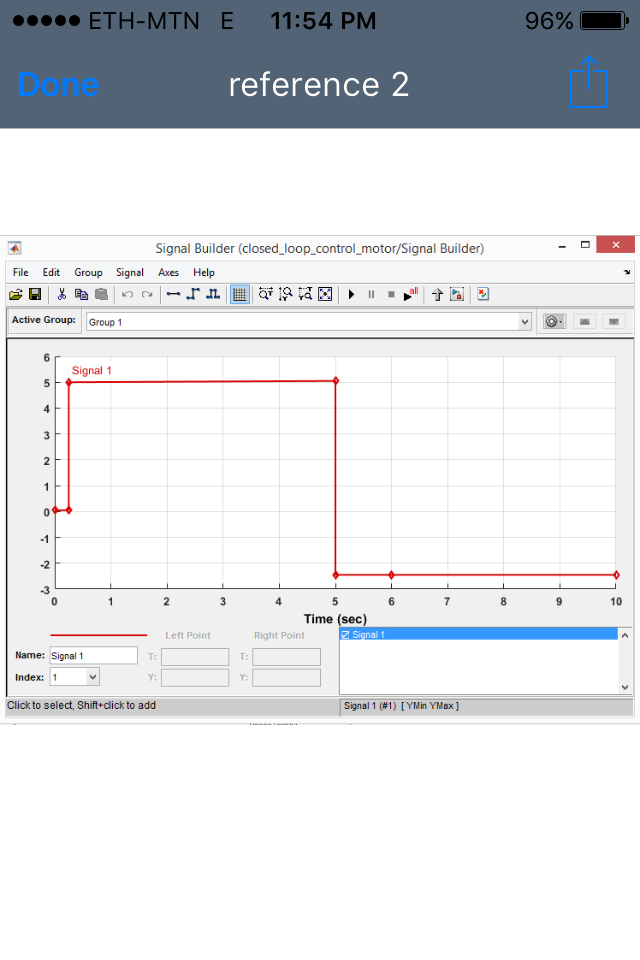
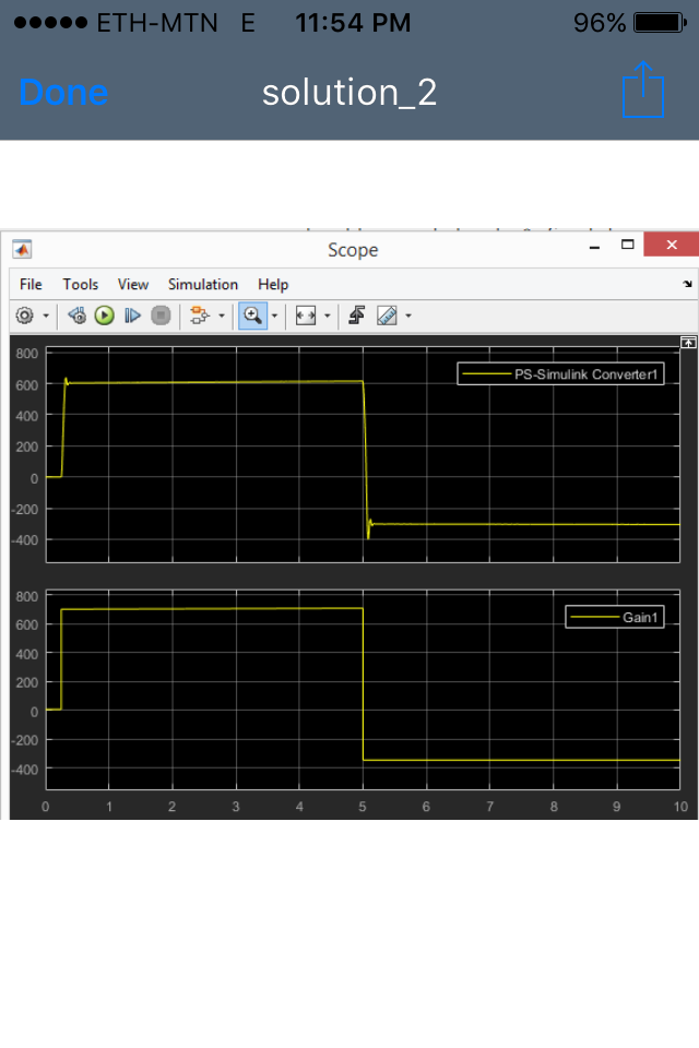 We can see from the picture that it went back to some desired location( or atleast a better one ). But i only changed my reference nothing else. I have done a small delay on the reference so that it is visible. I can even go furthur and delay it even closer to zero so that it would be as if the system works fine as shown below.
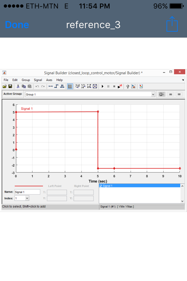
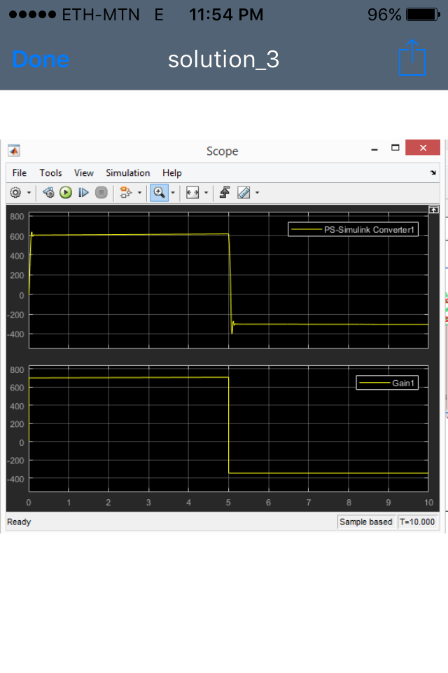
So what is this phenomenon? I really don't understand where this comes from? Why didn't the signal follow the reference on the first solution and then follow the reference on the rest of the solutions? Is it because of the algebraic loop errors? I really need your help because it has been frustrating me all day! For more information:
$K$ values on the figure simply convert from the voltage signal source to actual rpm values. It is found from steady state analysis by initial value theorem ( answers the question what is the voltage required to rotate the motor at some rpm value $w=K*V$
$PID$ controller is actually a $PI$ controller. I have set $D=0$ P is found root locus plot so that we have a better performance. P=0.04*K. $I$ Is set to 0.1 to reduce steady state error. Found from simple experimentation.
Saturation is set to 0 (lower limit) and 5 (upper limit).
