0
\$\begingroup\$

I want to interface 12 VDC rated WS2815B addressable LED strip with a 3.3 VDC microcontroller.

I am having difficulty finding a logic level shifter which translates 3.3 V to 12 V. Data rate is significantly high and hence fast rise and fall times are required. Timings are as below:

enter image description here

How do I tackle this problem?

Two things come to my mind:

1) Maybe there is a part which will do the job and I am not aware of it.

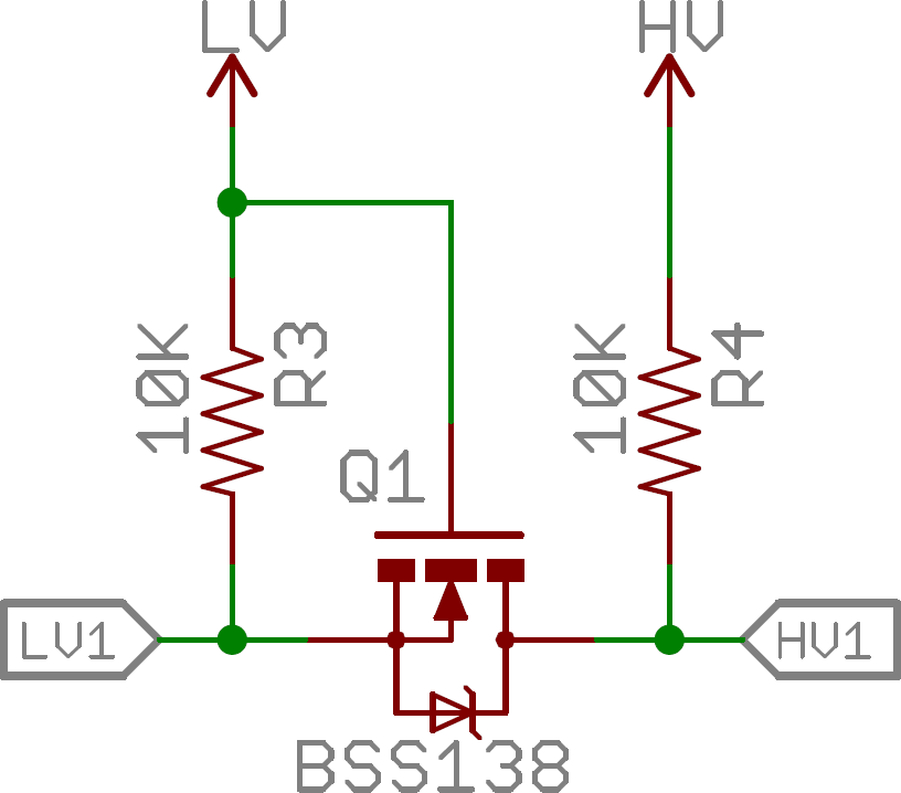
2) I need to implement logic level conversion circuit using basic components. - In this regard, I cam across some circuits as shown below:

logic level shifter

However on further reading, I found that these circuits can't achieve the fast rise and fall times required by ws2815b. Is there a better way which can solve my problem?

\$\endgroup\$
2
  • \$\begingroup\$ You misunderstand what you have, and how to drive it. It is powered by 12 volts, and the logic signals are 5 volts, and need to come from a MPU or Arduino or Raspberry Pi, as it takes complex command streams to sequence through colors and brightness levels. Each LED is a module with a serial interface, not a bare bones LED. Read the fine details please. \$\endgroup\$
    – user105652
    Commented Jan 8, 2019 at 6:40
  • \$\begingroup\$ @sparky256 - I do understand that it's not barebone LED. It requires command streams for color settings. Page 2 lists absolute max ratings where 9.5V to 13.5V is mentioned. I believe it means the strip needs 12 V as supply. On page 3 however, it mentions electrical characteristics. In parenthesis, it mentions VDD as 4.5V to 5.5V and then logic high is mentioned as 0.7 VDD. This is what is confusing me. \$\endgroup\$ Commented Jan 8, 2019 at 6:51

1 Answer 1

1
\$\begingroup\$

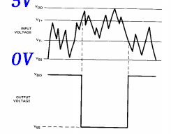
THe WS2815B operates on Vcc= 5V supply logic levels from 0.3 to 0.7 x 5V not the LED 12V supply. This means it is similar to the 5V CMOS Schmitt trigger input.

The LED supply is called \$V_{DD}\$ and intended for automotive 12V supply voltages or +9.5~+13.5

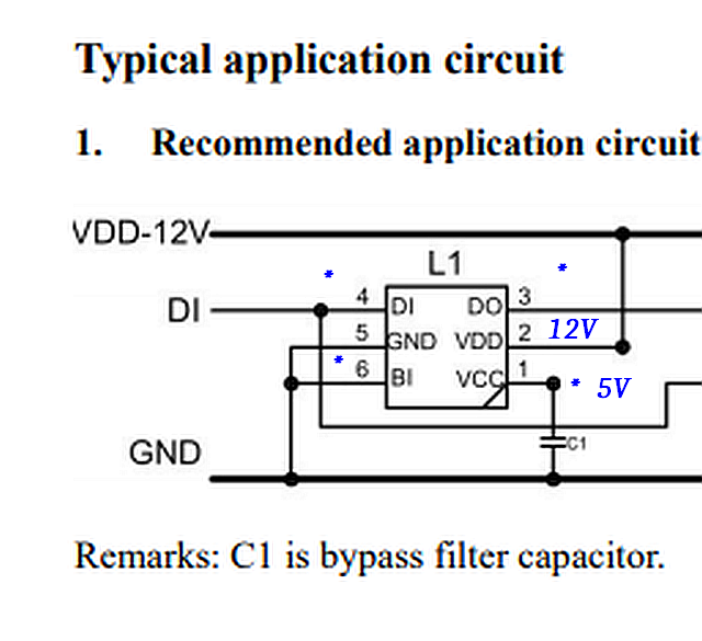
The Din Data port operates off \$V_{CC}\$ which is internally regulated and brought out for a Cap to added as an option. Check Pin1. It must be 5V.

Pins 3,4,6 are 5V logic level signals. BI on pin 6 is grounded only on the 1st chip.

======

The datasheet is a bit unconventional lacking in some details, so this confusion is expected.

They could have included something like this. enter image description here

Perhaps they assumed too much.

The chip ought to have diode clamps to internal 5V on the input from the 10k Pullup you used.

Your design looks ok except the pullup should be to pin 1 = 5V

Depending on the cable capacitance the 10k may need to be lowered towards 1k.


I added in BLUE

enter image description here

\$\endgroup\$
4
  • 3
    \$\begingroup\$ You changed your name again? Geeze... \$\endgroup\$
    – user105652
    Commented Jan 8, 2019 at 6:41
  • 1
    \$\begingroup\$ I wore many hats too. \$\endgroup\$
    – D.A.S.
    Commented Jan 8, 2019 at 6:44
  • \$\begingroup\$ Page 2 lists absolute max ratings where 9.5V to 13.5V is mentioned. I believe it means the strip needs 12 V as supply. On page 3 however, it mentions electrical characteristics. In parenthesis, it mentions VDD as 4.5V to 5.5V and then logic high is mentioned as 0.7 VDD. This is what is confusing me. \$\endgroup\$ Commented Jan 8, 2019 at 6:52
  • \$\begingroup\$ I feel that logic level should be according to 12 V. LED has DIN and DOUT pins. It also has a waveform correction feature where the data waveform is corrected before passing to the next LED. When I give a 5V logic to the first LED powered by 12V, it automatically raises the voltage levels to approx 10V for the next LED. \$\endgroup\$ Commented Jan 8, 2019 at 6:57

Your Answer

By clicking “Post Your Answer”, you agree to our terms of service and acknowledge you have read our privacy policy.

Not the answer you're looking for? Browse other questions tagged or ask your own question.