1
\$\begingroup\$

one of my electronic appliances has stopped working after several years of use, it is definitely beyond the warranty period however I've been unable to find any more recent appliances that beat it.

With this said, I have looked into repairing the device after repairing a previous one (thanks for those that helped with my previous question). The issue has been reported from various users of the appliance and a few seem to point to the safety capacitor being responsible.

Last time, I was advised to pick one like for like however there doesn't seem to be that much information on the capacitor itself and I am struggling to find the datasheet for the capacitor.

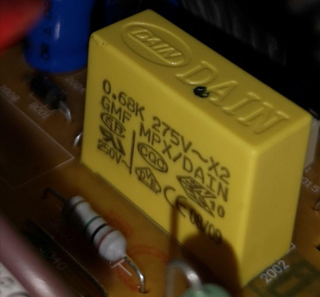
The capacitor

From my understanding the 0.68K means that it is 0.68uF +/- 10%. The voltage is 275V. I measured the outside of it (as it's still attached to the circuit board), it's 26mm(length)*9mm(width)*18mm(depth), height/width can be changed a little as there is space.

The only suitable replacement I have found isn't the right size (the others I have seen are +/-20%). ECQU2A684KLA

Would it be possible to add wires to the end of a capacitor to extend the pins so that it would match the holes for the pins on the circuit board? If so, what effect would this have? Would it reduce/increase the resistance?

Thanks.

\$\endgroup\$
3
  • \$\begingroup\$ Thanks for putting the question on hold however it's more about the learning aspect rather than repairing itself (I am not asking how to repair the device). I have edited it to make it clear I am asking whether it's appropriate to somehow extend the pins on a capacitor and whether I need any more information before replacing the capacitor. I am asking this due to the fact that it's a safety capacitor and with it being high voltage, I'd rather not try it with incorrect specifications or causing some sort of fire risk by attempting to extend the pins. \$\endgroup\$
    – Sam79
    Commented Jan 18, 2019 at 3:24
  • \$\begingroup\$ Putting wire leads on the end of anything will increase the resistance and inductance of the capacitor, if that is something that the circuit can handle, then do it. You'd need to know what kind of current is running through it to see if it is safe to do this. If this is on the AC mains line, it is most likely not safe as there are creapage and clearance requirements to prevent arcing \$\endgroup\$
    – Voltage Spike
    Commented Jan 18, 2019 at 16:33
  • \$\begingroup\$ Do you have a multimeter to test the capacitor with once you get it out of the circuit? \$\endgroup\$ Commented Jan 19, 2019 at 15:01

2 Answers 2

2
\$\begingroup\$

Looking at what little bit of the PCB you have in the picture this looks to be a part of a simple budget power supply like this:

schematic

simulate this circuit – Schematic created using CircuitLab

That's a very popular way of making a dirt cheap PSU for something which needs little current, or to bootstrap a larger SMPS. The safety caps often fail and then the whole device appears dead.

If that's the case the exact value of the capacitor isn't likely to be that critical, nor the length of the leads (you're dealing with low frequencies, and there's already plenty of resistance in series). Although, depending on how you extend them (bending them flat against the board at one end is popular), you'll want to be careful of making it easier to touch the live side.

You can also get axial X2 caps which might make it easier to fit your board, and you can always consider drilling a hole in the PCB for the lead if you don't compromise an insulation gap and the geometry of the tracks fits. But I'm surprised you can't find an exact fit - you don't give the lead pitch otherwise I'd find one.

-- edit --

your original capacitor's data is here

http://www.dain.com.tw/productd412.html?mod=show&cid=2&pid=MPX%28275VAC%29&lg=E

They give L=26.5, H=19, D=10 and pitch 22.5, given you referenced CPC I'm guessing you're in the UK, so an appropriate replacement would be RS 869-7431

which has L=25.5 D=10.5, H=19.5 and a pitch of 22.5 with a MOQ of 5.

https://uk.rs-online.com/web/p/polyester-film-capacitors/8697431/

\$\endgroup\$
1
  • \$\begingroup\$ Thanks for the help, it does seem to be a PSU from my understanding of the circuit board. Based on your answer I have decided to go for the safety capacitor you suggested as it seems like it would be a suitable replacement. I considered the option of extending the pins from the one I originally found however based on AnalogKid's answer mentioning it wouldn't be suited to high vibration environments I have decided not to go down this route. \$\endgroup\$
    – Sam79
    Commented Jan 22, 2019 at 23:25
0
\$\begingroup\$

The capacitor is a part of either an EMI filter or a very low power offline power supply. Either way, extending it above the pc board with short stiff wires will not affect its electrical performance. It will be significantly less rugged, so do not do this in a vibration environment. Can you post a wider image to show more of the surrounding components?

Also, where are you located? What you have is a box film capacitor with X2 rating. This is a common capacitor size and type, and broad line distributors such as Digi-Key almost certainly have an exact replacement. The lead spacing is an important dimension to limit the search.

DK has 15 different models in stock. From your photo it looks like height is not a problem. Start with accurate L, W, and spacing dimensions in mm.

https://www.digikey.com/products/en/capacitors/film-capacitors/62?k=.68&k=&pkeyword=.68&sv=0&pv1292=27&sf=0&FV=1430007b%2C14300017%2C14300019%2C1430001b%2C1430001c%2C1430001d%2C1430001e%2C1f140000%2Cmu0.68%C2%B5F%7C2049%2Cffe0003e%2Cc0003&quantity=&ColumnSort=0&page=1&stock=1&pageSize=25

\$\endgroup\$

Your Answer

By clicking “Post Your Answer”, you agree to our terms of service and acknowledge you have read our privacy policy.

Not the answer you're looking for? Browse other questions tagged or ask your own question.