0
\$\begingroup\$

I need to perform the Worst case analysis of the LED circuit attached. The value of the resistor has already been chosen and I am doing the calculations for min, typ and max current. LED circuit
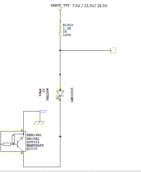
Please bear with this thread for the detailed explanation. Need to get some clarity.

I have three voltages 7.5V/13.5V/16.5V.

This is my LED Datasheet

The Operating temperature of my board is -40degC/+25DegC/+80degC

So, I need to perform WCCA with these parameters.

How shall I go about this? I need Min/Typ/Max values.

Please check if my approach is correct :-

I figured out that the total current through the R, LED and Transistor is Typ I = 13.5/1200=11.25mA

Max I = 16.5/(1200*1.03)=13.35mA (3% tolerance taken for R)

Similarly for Min I = 7.5/(1200*0.97) = 6.4mA

So, once I have these currents, I will now figure out the Vf of the LED with respect to the LED datasheet graph. (Vf vs If). So, I will have the Vf of the diode also. And since I have different temperatures to consider, I need a graph in the LED datasheet with provides a graph of "Change in Voltage" vs "Temp". So that I can add the change in voltage to the min Vf and subtract the change in voltage to the max vf af the temp of -40 and +80 respectively. However, in the datasheet mentioned, i donot have such a graph. But I have this graph in This Datasheet but it is a green LED. What can I do in this situation.

Suppose, I had done this Vf and temp calculation, I can now perform one more correct iteration of current through the LED by this formula,

I = (Vin - Vf - Vce(sat)) / R. // for all the temp and input voltage.

So , I will now have the near accurate value of Worst case analysis current values. Is my approach correct?

Please help me if I am wrong and tell the correct method. Will be really helpful. And what about the missing temperature vs change in voltage graph of the LED.

Thanks.

\$\endgroup\$
9
  • \$\begingroup\$ Always start with 10~25% below Absolute Maximum , then compute heat rise vs rating. Rja * I^2 R for each part needed . Note that the rating of 20mA is recommended and not 30 and Vf=2.0V @ 20mA +20%/-5% \$\endgroup\$
    – D.A.S.
    Commented Jan 19, 2019 at 16:39
  • \$\begingroup\$ I think you should talk to the instructor to see what they want you to do about the lack of data for the LED. We can all tell you what we would do, and some of us would be more conservative than others. However, without the necessary data on the variation of current with forward voltage and temperature it's hard to do it right. \$\endgroup\$ Commented Jan 19, 2019 at 16:43
  • \$\begingroup\$ You could use a Monte Carlo simulation. * Think about how precise your limits must be - you could choose to take more margin than needed * If you need to be precise, bare in mind that when you LED is on it heats up itself making its operating temperature higher than 80°C, same for your transistor. So if you want to be precise, you would also need to take into account the thermal resistance of the package, etc. * Your supply voltage also has tolerances! \$\endgroup\$
    – le_top
    Commented Jan 19, 2019 at 16:46
  • \$\begingroup\$ Thank you. Is my approach correct? \$\endgroup\$
    – Freshman
    Commented Jan 19, 2019 at 16:56
  • \$\begingroup\$ Am I doing the calcuations correctly? \$\endgroup\$
    – Freshman
    Commented Jan 19, 2019 at 16:57

2 Answers 2

1
\$\begingroup\$
And what about the missing temperature vs change in voltage graph of the LED.

Your link for the first datasheet did not work for me.

The graph you refer to is a graphical representation of the LED's Vf temperature coefficient.

From the green datasheet the Vf temperature coefficient is 0.0036 V per °C (°K).
The yellow datasheet should have the Vf temperature coefficient even if there is no graph.


While luminous intensity may not be relevant to WCA it should be noted that temperature has a huge effect on the luminous intensity of a yellow LED.

enter image description here

For WCA it is better to use the temperature coefficient rather than the graph.

The green datasheet states the Vf values (2.6V, 3.0V, 3.7) are at 25°C.

That should mean (for the green LED) at a case temperature of-40°C will add (negative coefficient) to the VfVf25° + (65° x 0.0036V) and at 80°C subtract (55° x 0.0036V) to the min, typ, and max values.

Regarding @SunnyskyguyEE75 answer, I would not be concerned with the Tja for this circuit.


Tja is not very relevant to an 20 mA circuit.

Even if using a high power LED, you cannot use the specified Tja as this spec is for a JEDEC test board for comparison purposes and is unlikely to represent your circuit board.

The junction-to-ambient thermal resistance, RθJA, is the most commonly reported thermal metric and is the most often misused.
Source: Semiconductor and IC Package Thermal Metrics


If you were to use Tja you would need to understand the thermal complexities of PCB design. IF you have an interest in PCB thermal management this is a good reference: Thermal Design By Insight, Not Hindsight

\$\endgroup\$
-1
\$\begingroup\$

WCCA is all about reliability for stress factors that increase with Temp or V or I and functional requirements with design specs like brightness and max hotspot.

In this case, it is simple with only a few parts.

Calc. Imax using V+max. Vf min, Rmin and 0.2V for transistor Vce.

Approx. for Yellow, @ Vmax, Imax=( 16.5V-2V-0.2V ) / 1.2k = 11.9mA so operating at 12/20=60 % of rated current so even 20% tolerance on these parts is ok.

Calc Imin @ Vmin, Imin=(7.5V-3.4V(Green)-0.2V)/1.2k= 3.25 mA

When approaching max raing, you need to compute temp rise.

Since there is so much margin WCCA is not warranted, but you may want to define your acceptance criteria.

other

e.g.

Note that for 1206 R's derating is the same as Rja ( junction to ambient temp resistance ) thus Rja(1206)= (155-70'C)/0.5W ['C/W] above max internal ambient temp, then prudent design criteria might say <100'C max. You will find your current and temp is too high.

Repeat for all hot parts including LED and ABS. MAX. means going above affects lifespan significantly. Do you feel lucky?

You learn by computing temp. rise. Then you remember this in future so it does not have to be repeated every time and remember what margin to use.

Note that the rating of 20mA is recommended and not 30 and Vf=2.0V @ 20mA +20%/-5% unless just experimenting. Otherwise, you must consider what copper area you have to dissipate heat under a tiny part in sq.cm/W.

Time savers include simulations, and modelling each part to remember in future like 170'C/W rise for a 1206 R. Ask what is the acceptable worst case hot spot for this design (from all sources of heat and component tolerances for you to estimate).

It gets easy once you learn this and how to model the equations for each part.

Like a Yellow LED might be Vf = 1.7V+If*Rs for Rs=15 +20%/-5% then add other parts to the loop current equation at worst case cold temp knowing the tempco. (temperature coefficient, like -4mV/'C for Vf).

It depends how rigorous, you need to be for WCCA. - Consumer, automotive, corporate, military, space, all have different requirements.

OK I'll do it once for you.

\$R_{tot.} = {(Rs_{LED} + Rce_{SOT363}+ R_{1206} \$

Pd(R)=If^2R= = 12mA* 1.2k

\$Vf_{LED}=1.7_{[V]}+If_{[A]}*15_{[Ω]} \$ for Vt~1.7 for Yellow ( 2.0V nom @ 20mA) , ~2.8V for Green at 1mA 3.1V nom @ 20mA for this size, approx.

\$\endgroup\$
8
  • 1
    \$\begingroup\$ Way overcomplicated for a series circuit. What you say is true for a whole system PCB/circuit analysis, but you would not do this for such a simple circuit. \$\endgroup\$ Commented Jan 19, 2019 at 17:33
  • \$\begingroup\$ You should if you never have done it before. Same applies to linear regulators. \$\endgroup\$
    – D.A.S.
    Commented Jan 19, 2019 at 18:04
  • \$\begingroup\$ This is just the method applied to a system exposed on a simple part of it. \$\endgroup\$
    – D.A.S.
    Commented Jan 19, 2019 at 18:25
  • \$\begingroup\$ Thank you for the detailed answer @Sunnyskyguy EE75. I have understood most of it. But why do you considered 12/20=60% of the rated current as standard and how you decide the 20% tolerance to be ok ? And can you just tell me order of the steps as points for this circuit WCA. What is the order of calculation.. please help. Thanks again \$\endgroup\$
    – Freshman
    Commented Jan 20, 2019 at 15:11
  • 1
    \$\begingroup\$ Do resistors really have an Rja? I believe you mean film temperature rather than junction. Tja specs are used to compare one component to another using a JEDEC test PCB and does not represent the values of a typical circuit board. Tja is going to have irrelevant effect on a 20 mA LED. If Tja were necessary, you would need to use Tjc to calculate Tja for your particular PCB. \$\endgroup\$ Commented Jan 22, 2019 at 3:08

Your Answer

By clicking “Post Your Answer”, you agree to our terms of service and acknowledge you have read our privacy policy.

Not the answer you're looking for? Browse other questions tagged or ask your own question.