0
\$\begingroup\$

I'm trying to put together a simple superhet radio, receiving at 161.75MHz (this is for AIS reception.) I've been trying to design around NXP's SA605 chip (see SA605) but I'm having a hard time figuring out what values to use for some components. My IF is 10.7MHz & the LO is 161.75 - 10.7 = 151.05MHz. I'd like to avoid using a crystal. From the docs, it seems like a Colpitts oscillator should do the trick, with L = 82uH and C = 27pF (I know this is off a little bit, but I assume I can put a trimming cap in parallel with the capacitor across pins 3 & 4 to get it right.)

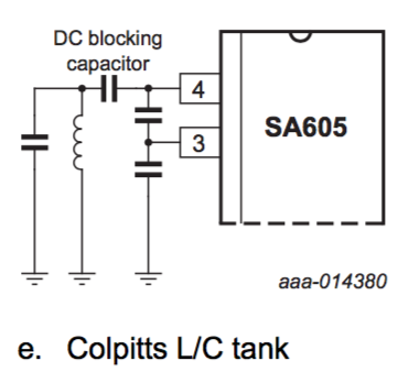
From one of the application notes, it looks like I can do this fairly simply:

SA605 Colpitts

...but the question becomes, what values do I use for the DC blocking cap, and the one on ground? I assume the value varies based on the oscillation frequency, but I don't know where to go to calculate that.

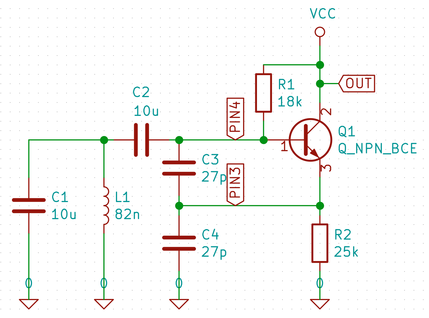
I've also tried to simulate this in the spice simulator now embedded in KiCAD:

SA605 + SPICE

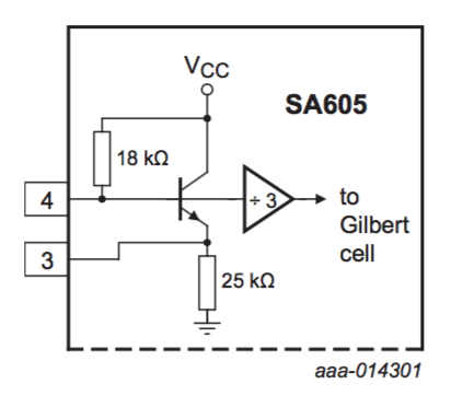
...using the equivalent circuit from the application note:

SA605 LO EC

...but I haven't had any luck getting it to actually oscillate. Do you have any hints on getting this going?

\$\endgroup\$
1
  • \$\begingroup\$ Your schematic shows 10uF in parallel with the inductor. \$\endgroup\$ Commented Jan 22, 2019 at 2:35

2 Answers 2

1
\$\begingroup\$

It seems that the local oscillator transistor has marginal gain at 150 MHz...achieving stable oscillation may be difficult. App-note suggests boosting DC operating current by adding an external resistor from pin 3 to ground: a value between 10K - 22K is recommended for oscillator frequency above 80 MHz. Boosting oscillator DC current will improve its gain-bandwidth product.
In addition, RF oscillator amplitude at pin 3 should be 220mV (RMS) to get full mixer gain. Relying on a SPICE simulation is very risky, because this transistor is not well-specified in the data sheet - what transistor should you substitute?

Oscillator frequency will drift with temperature and supply voltage. Expect to adjust frequency often (either with variable L or a variable C). At these frequencies, a voltage-controlled-oscillator would be used, as part of a phase-locked-loop to achieve stable frequency. Doing so with this feeble on-board transistor makes oscillator design even more risky.
An alternative might use a digital oscillator: something like SiliconLabs Si5351. Its top frequency end goes at least to 160 MHz (some claim 200 MHz). A tiny microcontroller would be required to set its frequency on power-up, and a fixed-frequency ~25MHz crystal is required as well. You can program its output frequency very close to 151.05 MHz. Its 3.3V CMOS output square wave can be reduced in amplitude with a resistor divider, and injected via a small capacitor to SA605 pin 4.

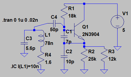
Colpitts oscillator: In the schematic below, R3 is an added external resistor to pin 3. R1 & R2 are internal bias resistors inside the chip. These might serve as a starting point for choosing values:
VHF Colpitts SA605 rough simulation
Oscillating frequency is roughly 150 MHz. C3 could include a very small variable capacitor, or L1 might be wound on a form with an iron powder slug or brass slug. R4 is not a real resistor; it simulates finite Q of the coil L1.


This simulation kick-starts the oscillator by injecting a current pulse with an initial condition: .IC I(L1)=10n

\$\endgroup\$
2
  • \$\begingroup\$ Amazing work -- thank you! A note, and a question: it seems like the best way to figure out component values is to actually build something rather than play with the simulator. And, I can use a square wave generator for the LO? I didn't think that was an option -- shouldn't it be sinusoidal? \$\endgroup\$ Commented Jan 22, 2019 at 9:20
  • \$\begingroup\$ I start by choosing the resonator L reactance about 100 ohms @ 150 MHz., then see if capacitor values are reasonable. Yes, most mixers accept square waves but you should include a frequency-selective filter (162 MHz) between antenna and mixer RF port. \$\endgroup\$
    – glen_geek
    Commented Jan 22, 2019 at 15:39
1
\$\begingroup\$

You need to inject a couple of cycles at the required frequency into the circuit between the inductor and Gnd, to get the simulated oscillator going. In a real-world circuit there is always some noise present that has the same effect.

\$\endgroup\$

Your Answer

By clicking “Post Your Answer”, you agree to our terms of service and acknowledge you have read our privacy policy.

Not the answer you're looking for? Browse other questions tagged or ask your own question.