0
\$\begingroup\$

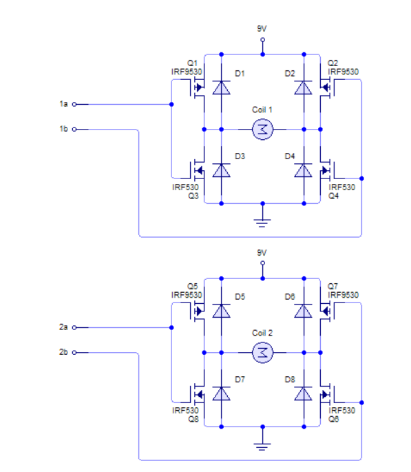
I'm working on a dual H bridge for a bipolar stepper motor. I found these two designs. I would like to know which design would you guys recommend and why? and if there is any component that might be implemented to any of the designs to prevent any damage to the motor or to improve it's performance. The transistor that I will use are 2N7000, SUP90P06 and IRLZ44.The motor will be powered by a Lipo battery (11.1V, 25C, 2200mhA). The motor that I would be using has these characteristics:

Rated Voltage: 3.6V DC

Rated Current: 1.2A/phase

Winding Resistance: 8.8±10% ohms / phase

Winding Inductance: 3.5 mH±20 %( 1kHz 1V rms)

Holding torque: 185mN.m Min (Bipolar)

insulation resistance: 100Mohms Min (DC 500V)

for the first configuration I would have to build two setups like these since it's a bipolar motor. enter image description here
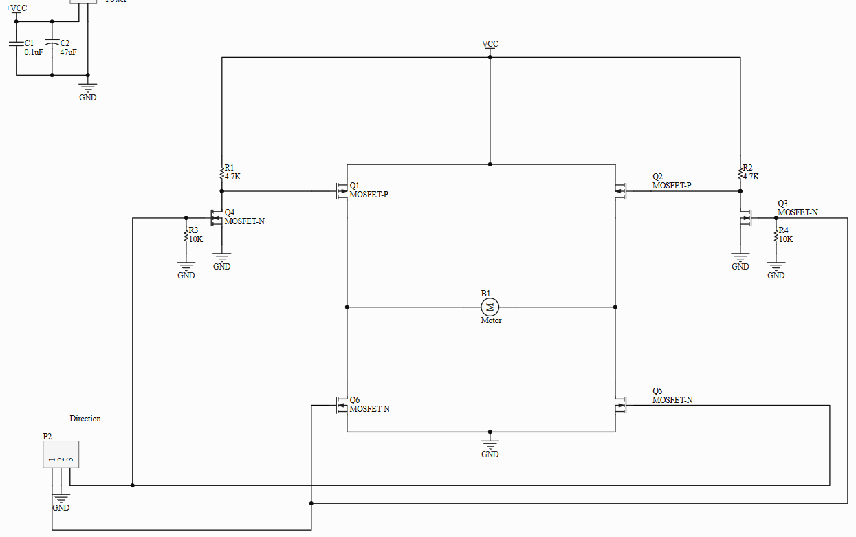
and the second design is here, for this setup up I would add 100 ohms resistors for each of the inputs coming from the MCU to the gate pins. This design doesn't require the additional 2 N mosfets from the first design.

enter image description here

Thanks!

\$\endgroup\$
2
  • \$\begingroup\$ Your requirement seems within the range of modern driver chips like the A4988, DRV8825, etc commonly sold assembled on inexpensive plug-in modules for 3d printers, which incorporate the chopping current regulator circuitry needed to get good performance from steppers, something your effort lacks. Is there a particular reason you are trying to build something from discrete FETs? Also note that batteries and steppers are not a very good fit for each other. \$\endgroup\$ Commented Jan 21, 2019 at 23:31
  • \$\begingroup\$ Something seems off about your voltage/current/resistance (Ohm's Law). If the applied voltage is 3.6 volts and the resultant current is 1.2 Amps, the phase resistance should be 3 ohms, not 8.8 ohms. Are you adding a resistor in series with the motor winding? Also, apparently you are not measuring the phase current anywhere.....for current control. Although, it would probably be better to use a driver chip as already mentioned. \$\endgroup\$ Commented Jan 22, 2019 at 23:04

1 Answer 1

1
\$\begingroup\$

The second circuit can work, but only under circumstances which are extremely unlikely. The problem is that

This design doesn't require the additional 2 N mosfets from the first design.

but it does require that the two control lines swing between 0 and 9 volts.

Let's say that your MCU outputs swing between 0 and 5 volts. Then the two p-type MOSFETs Q1 and Q2 will have gate voltages from gate to source, of -4 and -9 volts. In neither case can you guarantee that those FETs will ever turn off. Then whichever n-type is turned on will cause a short from 9 volts to ground.

And that will not make you happy.

I am, of course, assuming that your MCU pins do not go from 0 to 9 volts. Correct me if I'm wrong.

\$\endgroup\$
3
  • \$\begingroup\$ yep, the pins from the MCU go from 0 to 5V. should I still add the 100ohms resistor for each of the signals coming the MCU? I read in another post that they are for stability. Thanks again \$\endgroup\$
    – pekoms
    Commented Jan 21, 2019 at 23:21
  • 1
    \$\begingroup\$ @pekoms - Go ahead and add them or not, whichever you like. Did you miss the fact that THE CIRCUIT WILL NOT WORK? Just curious. \$\endgroup\$ Commented Jan 21, 2019 at 23:32
  • \$\begingroup\$ I was referring to the first design lol \$\endgroup\$
    – pekoms
    Commented Jan 21, 2019 at 23:33

Your Answer

By clicking “Post Your Answer”, you agree to our terms of service and acknowledge you have read our privacy policy.

Not the answer you're looking for? Browse other questions tagged or ask your own question.