0
\$\begingroup\$

I would like to understand a problem which i have with a little MOSFET test with a dc motor. My power supply drive the motor at 12V and it consume 1A.

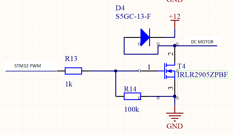
My circuit is very basic. I have a stm32 MCU which drive a mosfet (IRLR2905ZPBF).

enter image description here

My motor is connected between the dc motor output and the ground. I don't need a H-Bridge.

When i increase my PWM ratio softly from 0 to 100% my dc motor works prefectly but when my motor is stopped and i put a 100% value on my pwm command, there is a big surge (i think to start the motor from stop state). So my 12V power supply is falling and i obtain a MCU reset.

I had a 100uF bulk capacitor but no better results.

Thank you very Much.

Adrien

\$\endgroup\$
4
  • \$\begingroup\$ Are you sure your motor is connected to the output and ground? I can't see how it would have worked. Is it really connected between the output and the +12v? \$\endgroup\$
    – HandyHowie
    Commented Jan 25, 2019 at 9:58
  • \$\begingroup\$ Sorry my motor is connected between the output and the +12V. \$\endgroup\$
    – Volt
    Commented Jan 25, 2019 at 15:57
  • \$\begingroup\$ I found an interesting thread on the same topic : electronics.stackexchange.com/questions/146561/… \$\endgroup\$
    – Volt
    Commented Jan 25, 2019 at 16:11
  • \$\begingroup\$ I'm voting to close this question as off-topic because it has been abandoned by an asker who left severe errors in the problem description. With the asker uninterested in staying involved in the question it is unlikely anyone else will be able to provide an accurate answer. \$\endgroup\$ Commented Sep 20, 2019 at 5:06

2 Answers 2

1
\$\begingroup\$

Do you happen to have an oscilloscope that you can use to look at the power supply? If you do, look to see if you are seeing an initial dip in the power supply. You may be having a very brief dip in the power supply due to the surge current. That dip could have a fall time of a few nanoseconds. If that is what you are running into, then a 100 uF bulk capacitor has so much lead inductance and it will act as though it is not even there. In that case, you need to add something like a 0.1 uF ceramic capacitor with very short leads instead. The bulk capacitor supplies the long duration burst of current and the small decoupling capacitor(s) take care of the spikes.

\$\endgroup\$
4
  • \$\begingroup\$ When i observe the +12V Power supply, i can see the +12V is falling to 2V. That's the minimum voltage to supply my MCU. \$\endgroup\$
    – Volt
    Commented Jan 25, 2019 at 16:06
  • \$\begingroup\$ My Step-Down Voltage Regulator 3.3V is depending from the +12V Power Supply and there some capacitors on the 3.3V line. I think my MCU is preserved from very brief dip due to theses capacitors. \$\endgroup\$
    – Volt
    Commented Jan 25, 2019 at 16:08
  • \$\begingroup\$ Are you seeing a dip in the power supply on the output of the 3.3 volt regulator? If the input of the regulator is dropping to 2 volts, then there is a very good chance that the output is dropping as well. If that does not yield any insights as to what is going on, you might want to check the RCC_CSR register to see why the processor reset. You can find an article on how to do that at micromouseonline.com/2012/03/29/stm32-reset-source. \$\endgroup\$
    – AllenJones
    Commented Jan 26, 2019 at 5:50
  • \$\begingroup\$ Also, if you find that the 3.3 volt power supply is dropping too low, you could insert a diode in the line that goes from your bulk 12 V power supply to your 3.3 V regulator. It could be that the surge current due to the motor is sucking most of the energy out of the capacitors that are on the input of your 3.3 V regulator. The diode would prevent that from happening. \$\endgroup\$
    – AllenJones
    Commented Jan 26, 2019 at 5:56
0
\$\begingroup\$

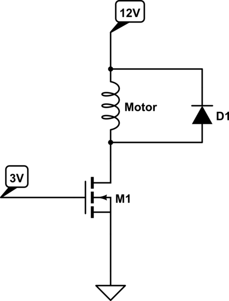
From your schematic, it does not look like the motor is connected properly.

Stopping a motor quickly will generate a large negative voltage spike called back EMF. To mitigate this, you can install diodes in reverse bias across the motor. This provides a resistive route for the energy which dissipates it quickly. You can install a second diode in series to increase the rate.

schematic

simulate this circuit – Schematic created using CircuitLab

\$\endgroup\$
4
  • \$\begingroup\$ What is different between yours and the OP's schematic? \$\endgroup\$
    – HandyHowie
    Commented Jan 25, 2019 at 8:52
  • 1
    \$\begingroup\$ My motor is actually connected to 12V \$\endgroup\$
    – MIL-SPEC
    Commented Jan 25, 2019 at 9:00
  • \$\begingroup\$ Sorry my motor is connected between the output and the +12V. \$\endgroup\$
    – Volt
    Commented Jan 25, 2019 at 16:01
  • \$\begingroup\$ That is not what you have drawn \$\endgroup\$
    – MIL-SPEC
    Commented Jan 29, 2019 at 8:06

Your Answer

By clicking “Post Your Answer”, you agree to our terms of service and acknowledge you have read our privacy policy.

Not the answer you're looking for? Browse other questions tagged or ask your own question.