1
\$\begingroup\$

Briefly the project I'm working on is made up of a blue pill, rotary encoder, acs712 30 amp current sensor and an OLED display. Everything is in functional state. The aim is to provide a stable controllable voltage starting from a 4s (16.8v max) lithium, BMSed, battery. At start I tought I could just use a good MOSFET and smooth that out with a filter on the output. Later on I discovered these xl4016 modules around the web Xl4016 module(xl4016 datasheet) that give 8 amps (which is a good start, there's also a 12 amp model) and these seems to give a stable output without much hassle. So the plan now is to control the vari-volt which on the board is made by a potentiometer. Looking around for a solution I found some possibilities:

  • generate a pwm signal, smooth it out trought a low pass filter, and feed it to feedback pin trough an opamp in voltage follower mode.

  • use a digital potentiometer (don't know if there's one up to spec)

  • use a DAC such as mcp4275

So the question is which one is the right way?

Additionally, tapping in the feedback pin could interfere with the xl4016 feedback mechanism. So the aim would be also keep that voltage stable (between 0-12v) even though battery is discharging, so I somehow should sense the battery voltage and the output voltage? In the project every cell voltage is monitored trough voltage dividers. Can I just use an external ADC? Thanks for the attention, and just ask for whatever is needed to provide an answer.

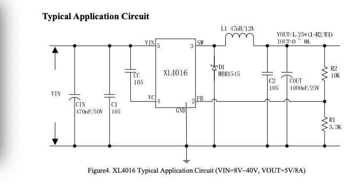
Update: datasheet here in the datasheet I can see : Vout = 1,25 (FBK) * (1+R2/R1) ----> if we put a fixed 10k resistor instead of the pot, can I inject voltage somehow on the feedback pin, maybe with a DAC? To get let's say a 12 V out following the formula it should be 2.97 V.
\$\endgroup\$
19
  • \$\begingroup\$ Your datasheet link is broken. \$\endgroup\$ Commented Jan 28, 2019 at 13:08
  • \$\begingroup\$ So you're trying to control the output voltage without having to turn the pot? That feedback voltage is fed to an Error Amplifier which compares it against a reference voltage. If you can find that reference voltage pin on that board you can cut the trace and use your uC DAC or an external DAC to make the reference voltage yourself. \$\endgroup\$
    – Stiddily
    Commented Jan 28, 2019 at 13:11
  • \$\begingroup\$ Datasheet fixed. @Stiddily This is another viable way. But what would be the relation between? Or in other words, shouldnt this reference voltage be fixed as reference? \$\endgroup\$ Commented Jan 28, 2019 at 13:17
  • \$\begingroup\$ Your output voltage is checked against a reference voltage in the Error Amplifier. The output of the error amp is related to how far off your output voltage is from this reference. This is then fed into a PWM amp that compares that signal to a ramp and creates the PWM signal. If you lower the reference then you lower the output voltage required for the error amp to say you're at the right voltage. (If you want more info on how the feedback works let me know, but I don't want to go off topic. I design power supplies for a living so I like to talk lol). \$\endgroup\$
    – Stiddily
    Commented Jan 28, 2019 at 13:54
  • \$\begingroup\$ @Stiddily If you have more info on the feedback glad to hear. I updated the post with typical application. To me it looks that the pot on the board is used to vary the voltage to the feedback pin. So assuming i can inject a clean and stable voltage to the feedback pin I can mostly regulate everything. Following the formula and keeping fixed 10k and 3.3k resistances, with a 3,3v max out I would likely be able to arrive to vout= 3,3* 4,03= 13,29 v which is perfect because I need 12v max. So your suggestion is to use a DAC or I can follow other routes? \$\endgroup\$ Commented Jan 28, 2019 at 14:01

0

Your Answer

By clicking “Post Your Answer”, you agree to our terms of service and acknowledge you have read our privacy policy.

Browse other questions tagged or ask your own question.